New Swingarm In Progress

Blaner

Your Friendly South African Ambassador
Mar 26, 2008
3,277
184
114
38
East London, South Africa
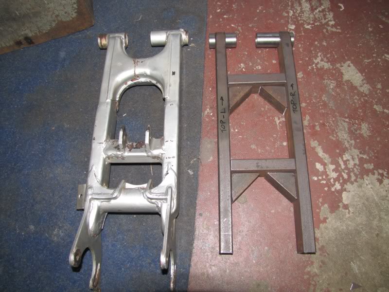
Well my swingarm cracked, its rusty inside and since I extended it and put the banshee 2+2 axle in its been having a hard time and showing some metal fatigue.

I decided to construct a new one...if you look here: http://www.blasterforum.com/suspension-14/rear-suspension-geometry-new-swingarm-44893/#post560668 you will see i did some geometry homework before I started...

anyway, my needle rollers and bushes were worn pretty bad, and since they cost and arm and 2 legs, i made another plan to get another life before having to buy new rollers and tubes.

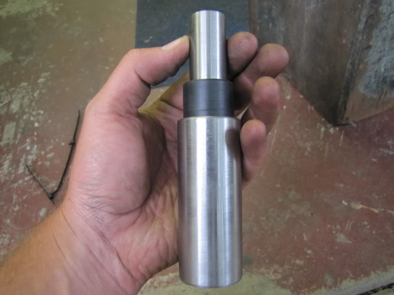
I got a guy to turn down the inner tubes to get rid of the pitting and then to make me matching vesconite bushes instead of the needle rollers...

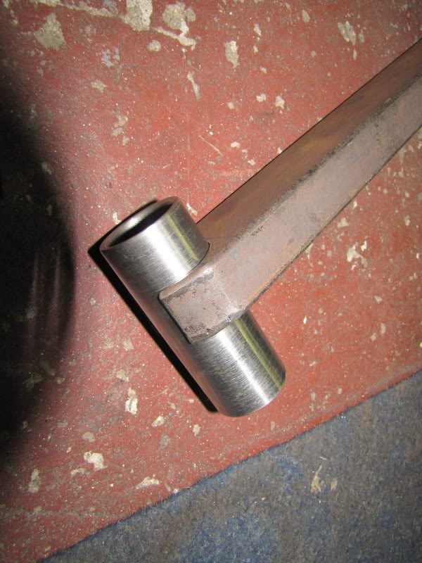
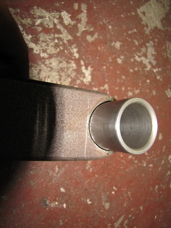
While he was at it i got him to make me some tubes for the swingarm setup, they are a custom size and you cant purchase the correct size pipe from the shop.

here they are...

IMG_2265.jpg


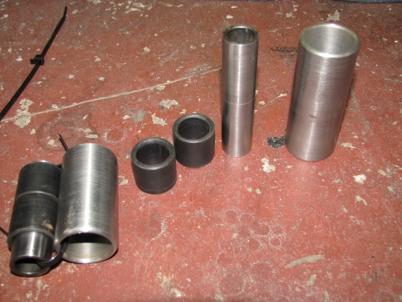
When these wear out, i will get new tubes and needle rollers from yamaha.

IMG_2266.jpg


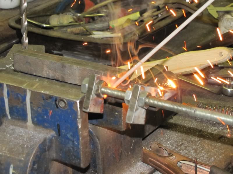
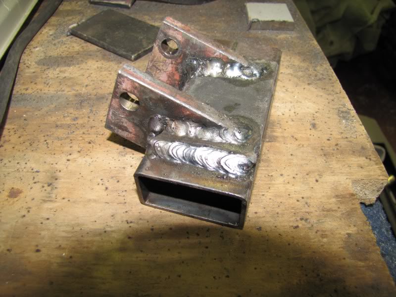
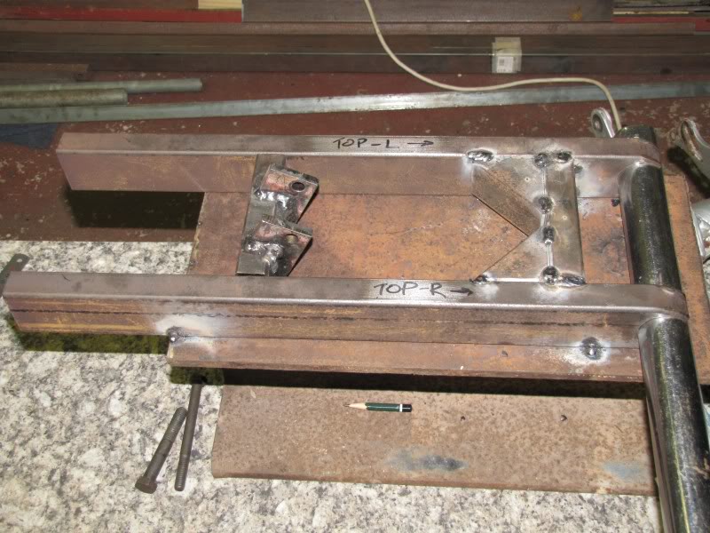
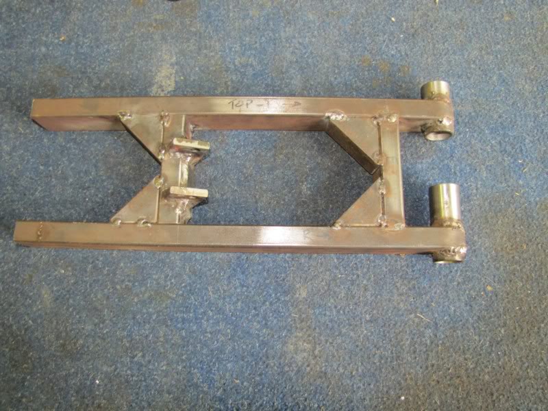
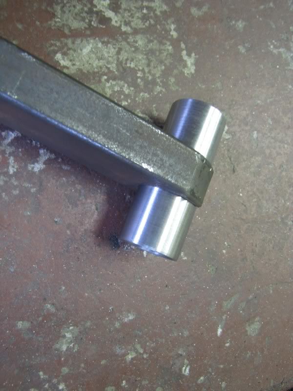
Then i got some of this: 50x25x2mm
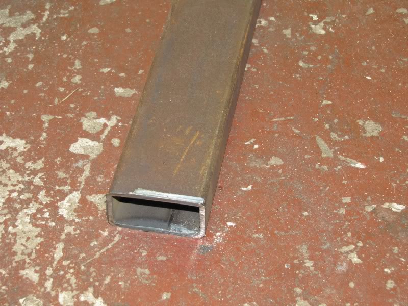
IMG_2267.jpg


and this:

IMG_2268.jpg


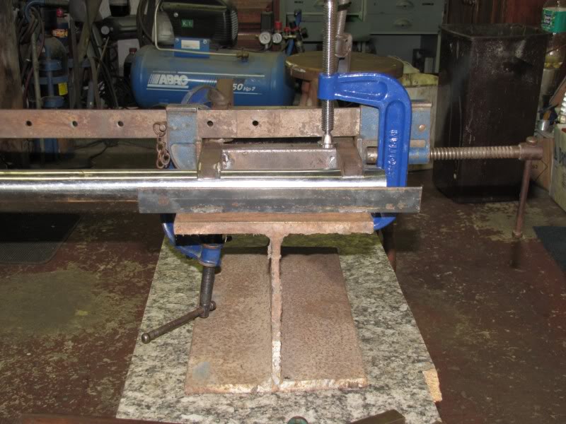
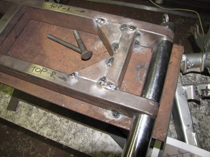
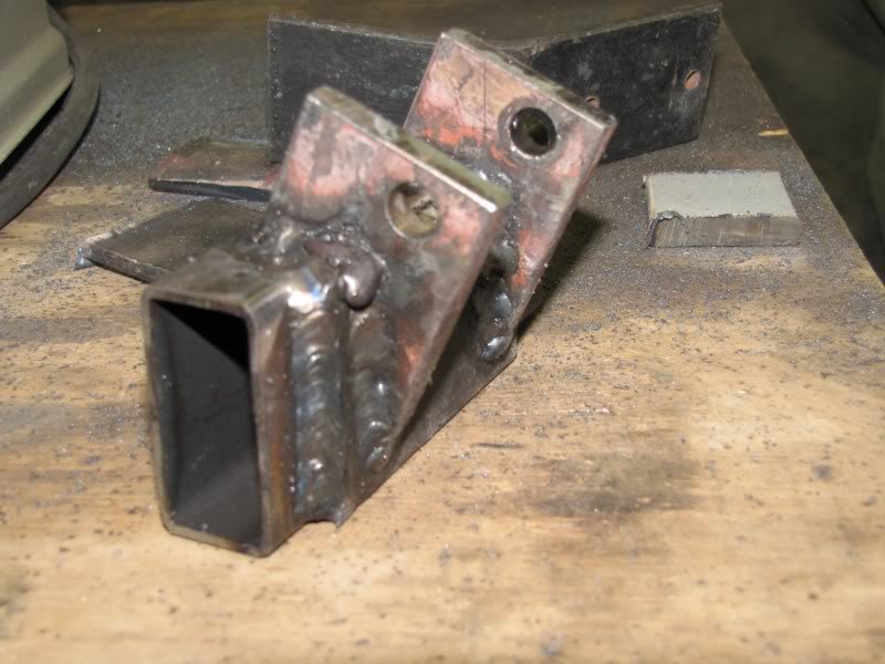
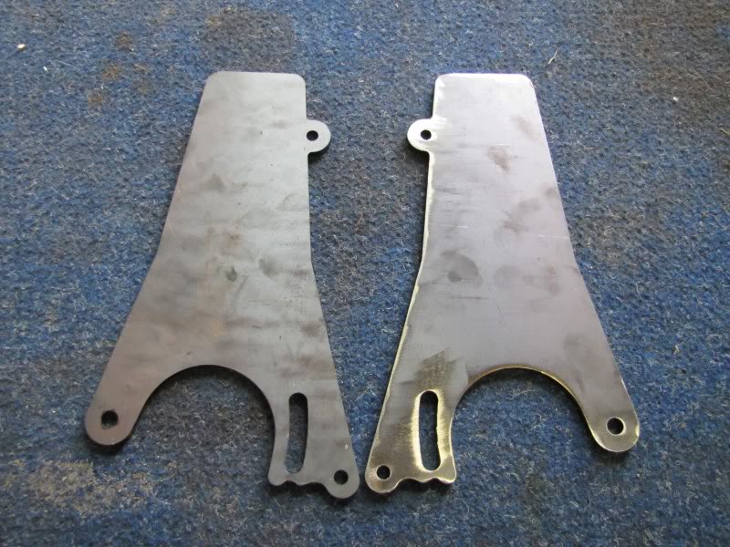
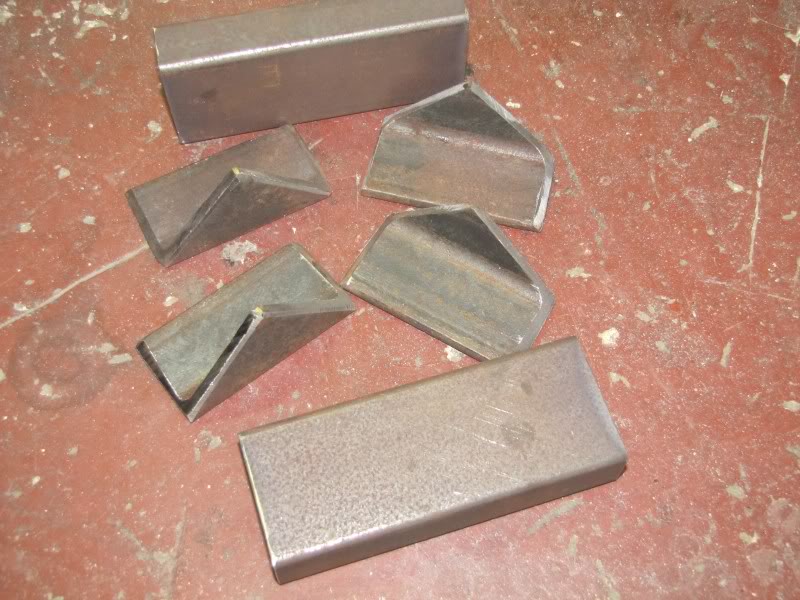
and I also got some 40x40x6mm angle iron and made these:

IMG_2270.jpg


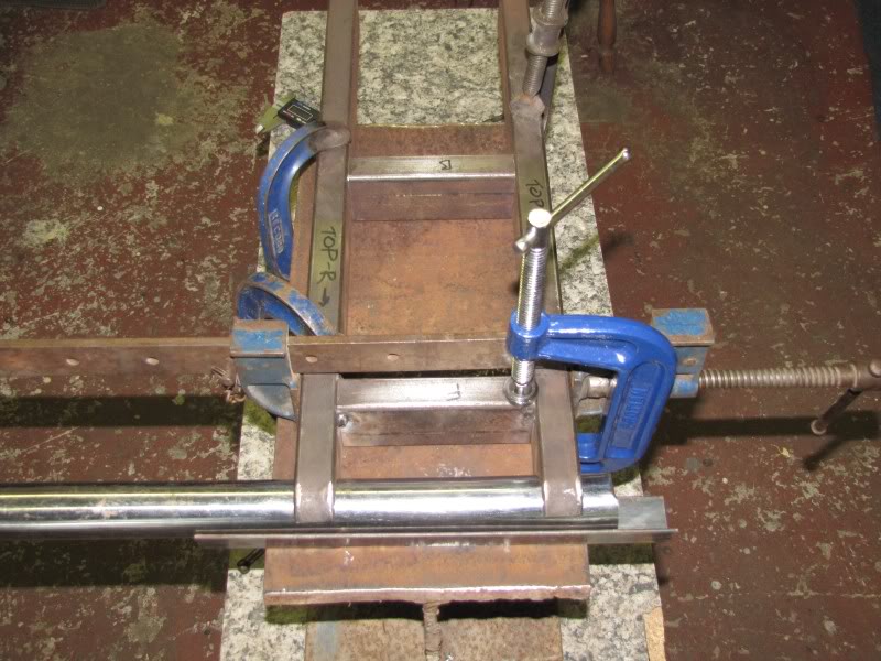
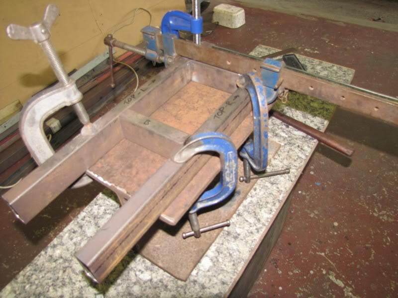
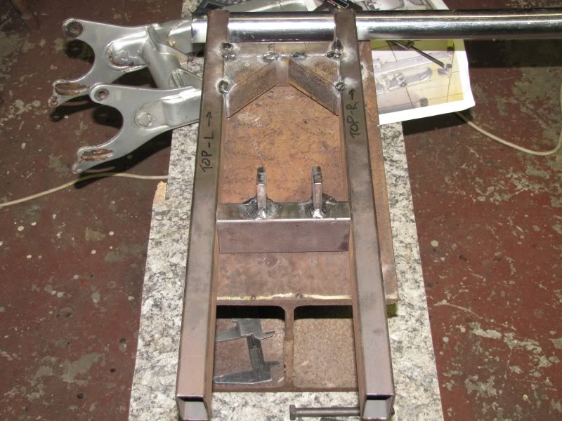
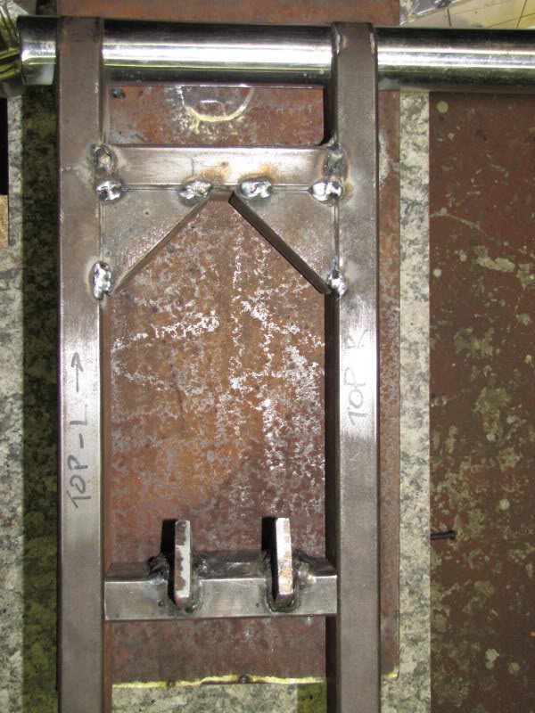
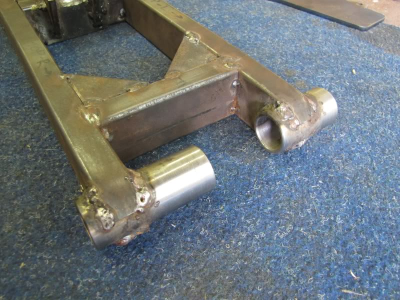
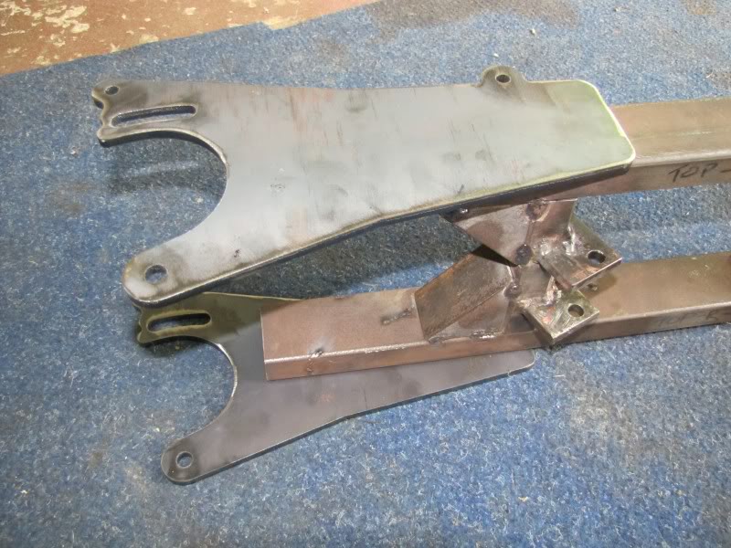
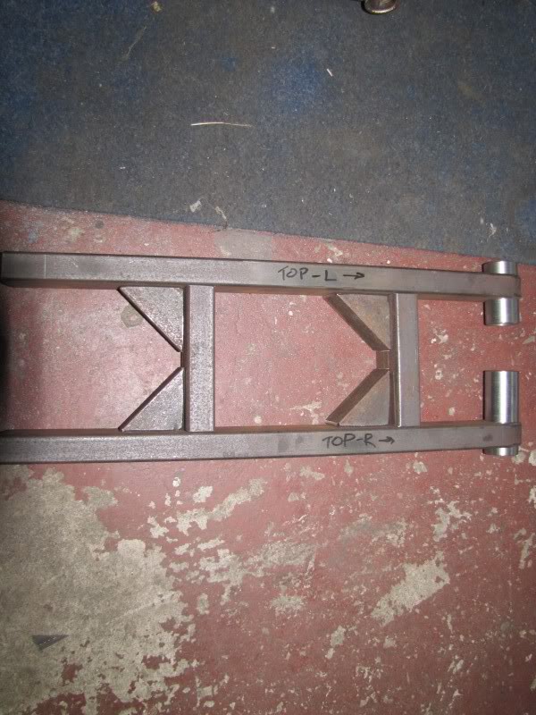
Then I cut these and measured and drilled and hacksawed and filed untill I had this:

IMG_2271.jpg


IMG_2272.jpg


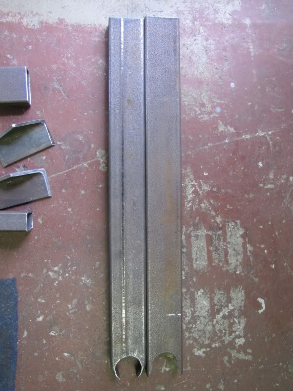
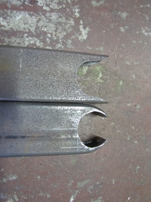
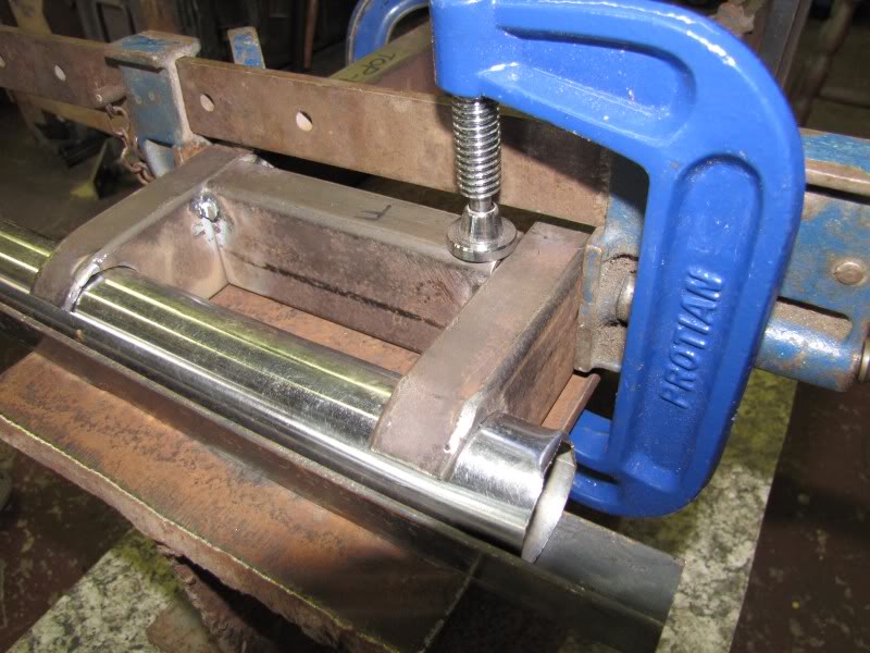
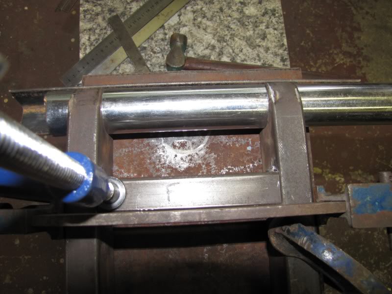
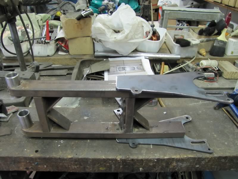
You can see i have worked the one but not the other...this was to that I could do this:

IMG_2273.jpg


IMG_2274.jpg


IMG_2275.jpg
 
here is a mock setup...it all seems a bit lightweight in the pic but more gussets are to come...

IMG_2276.jpg


IMG_2277.jpg


Johnswitch - a member on here emailed me the CAD design for the end "wings" those are currently at the laser cutting place but they are still closed for Christmas holidays and open on monday, so i will have to wait a bit for that! - many thanks to JohnSwitch for his help!

I will keep you posted with more detail soon!
 
lookin awesome so far, you've really done you're homework bro !!!!!!!
i'm tuned in for this big time
 
are you just spacing them side pieces any old where, or is one gonna be spaced so the shock mount attaches ???
as of now, one looks too far forward, and one too far back ??????
 
are you just spacing them side pieces any old where, or is one gonna be spaced so the shock mount attaches ???
as of now, one looks too far forward, and one too far back ??????

yes Awk, this was a very basic mock up, i just put the pieces on the floor where they more or less go so i could get a pic.

I spent the better part of last night setting up the front pipes with the motor clearance and also the overall width, this is quite tricky and very important because if its not right, the whole swinger and axle will be out of line and/or it wont fit around the motor.

il have some shots of how I set this up soon.

lots of measuring and mathematics...even old Pythagoras came to the party!I:I
 
Nice work! ... very interested ... I've got the same size tubing for mine ... It's a little narrower than stock so I was kinda nervous bout it ... You've encouraged me ... are you making any kind of fixture to keep it aligned while you weld ... thanks for all the pics.
 
Nice work! ... very interested ... I've got the same size tubing for mine ... It's a little narrower than stock so I was kinda nervous bout it ... You've encouraged me ... are you making any kind of fixture to keep it aligned while you weld ... thanks for all the pics.

i thought you were a swingarm champ!!?? yes the stock tubing is about 50x30 rectangular, so mine is a narrower, this means that i had to do some maths to keep things in line... i need the outside width to be the same as the stock or else my sums with lining up the swingarm perfectly are going to be compromised, so ive done that but then had to work out how wide the inside width would be and cut the struts/shock mount accordingly. coupled to this is the axle carrier plates that need to be inserted at the right width apart. so where to cut the slots for them also needs be worked out. Im still waiting on them.

I didnt get anything done today--took Sunday off and got in some R&R :)

im not going to make a jig...its too much PT. i have setup a system to get the front tubes aligned and will put some pics up tomorrow of that. im using a big capentry clamp and lining everything up with set squares and spiritual levels etc...should work out well.
 
OK! made some progress today. I spent the better part of the morning working with the front tubes and trying to align them properly. Felt like I was working in circles and couldnt get to the bottom of why my measurements wouldnt match my calculations..eventuall I found I was adding a certain figure instead of subtracting! EISH! my bad. anyway, i ditched that idea anyway and got hold of this piece if I-Beam and made sure it was flat and then setup the legs etc and made sure all was square, then i tacked the legs onto the I-Beam:)

My new idea involved using a solid pipece of pipe, the same OD as the machined tubes i am going to use, however it is very thin walled. The advantage of this is that it connects the left leg with the right, working with them as independants was difficult and also is looking for alignment trouble. This is temp and will be replaced by the real thing soon. It helped big time getting things straight

IMG_2280.jpg


IMG_2281.jpg


IMG_2282.jpg


IMG_2283.jpg


IMG_2284.jpg


Once i had the legs tacked down I tacked in the first cross member as well as the gussets

IMG_2287.jpg


WELDING :)

IMG_2288.jpg


IMG_2289.jpg
 
Next I made a creative shock mount. Now i didnt get a pic of the loose pieces but you can see what im getting at here, I tried to keep an angle similar to that at which the shock lies, but i wanted to keep the cross member upright, so I cut out some fancy wedge shapped goodies and attached them onto a 8mm plate which of you look carefully you may see! Then we cut away a 5mm gap between the shock mounts to allow clearance for the shock to fit in. Once i had the mounts on the plate, it was stuck onto the cross member...The plate also serves to give clearance away from the cross member so that the shock doesnt hit that by moving the mounts further forward.

i drilled the holes first once i had shaped the upright pieces and before they were welded fast onto the plate. Now finding this hole location was tricky. I wanted it as low as possible to give me maximum travel. However the limiting factor here is being able to fit the bolt! so i make the hole 5mm up from the axis of the top of the swingarm legs. Any lower and i will never get the bottom shock mount bolt in and the bolt head will hit the leg of the swinger. so these holes are as low as I can go! the shaped metal uprights allowed me to go lower without twisting the cross member, So I should still have the same travel if not a touch more than what I had before :)

Welds need to be cleaned up a bit still

IMG_2292.jpg


IMG_2293.jpg


Here it is positioned, still must carry on and attach the shock mount cross member tomorrow

IMG_2294.jpg


IMG_2295.jpg


IMG_2297.jpg
 
Last edited:
2.5mm mild steel rods and a DC welder.

Got the shock mount cross member in today as well as the tubes at the front. Everything is turning out nice and square, but it takes some effort and patience to make sure it is
 
well today i finally got my parts from laser cutting. Here they are 6mm mild steel

IMG_2300.jpg


In the mean time, the front tubes have been attached and aligned...

IMG_2302.jpg


IMG_2301.jpg


So now, a 6mm slot needs to be cut up the legs so that the wings can fit inside the rectangular tubing. Working out the correct width apart is very important

Here they are just placed ontop and underneath the swinger as it.

IMG_2299.jpg


IMG_2303.jpg


Should be done soon! im looking forward to seeing the finished thing. At the moment its quite a bit lighter than the original one