Here is a little something my brother put together as a "get the picture" graph.
The 1st graph shows a 2 stroke pilot circuit and how the various jet sizes for a Mikuni carb (stock blaster) correlates with the turns of the air screw and how it all effects air/fuel mixture
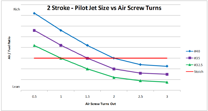
the red line stoiche (equilibrium) indicates the point at which the mixture is the same but with different pilot jets at different settings. In other words, a 32.5 stock pilot jet set at 1 turn out can run exactly the same IN THEORY as a 40 pilot at 2 turns out. HOWEVER, PLEASE NOTE this is not based on actual tests and is just a illustration of how the system works. it is not likely that a 40 will yield the same results at 2 turns as a 32.5 at 1 turn. more like 4 turns out which is impossible so its just a "not to scale" illustration.
So turning in the screw RICHENS the mix. turning it out LEANS the mix
Here is the 4 stroke version!
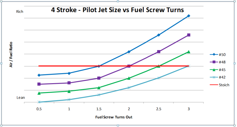
Note that a 2 stroke and a 4 stroke work opposite to each other. a 4 stroke uses a FUEL screw while a 2 stroke uses a AIR screw!
otherwise the same principle applies. BUT
So turning in the screw LEANS the mix. turning it out RICHENS the mix.
Hope this helps someone understand better!
The 1st graph shows a 2 stroke pilot circuit and how the various jet sizes for a Mikuni carb (stock blaster) correlates with the turns of the air screw and how it all effects air/fuel mixture
the red line stoiche (equilibrium) indicates the point at which the mixture is the same but with different pilot jets at different settings. In other words, a 32.5 stock pilot jet set at 1 turn out can run exactly the same IN THEORY as a 40 pilot at 2 turns out. HOWEVER, PLEASE NOTE this is not based on actual tests and is just a illustration of how the system works. it is not likely that a 40 will yield the same results at 2 turns as a 32.5 at 1 turn. more like 4 turns out which is impossible so its just a "not to scale" illustration.
So turning in the screw RICHENS the mix. turning it out LEANS the mix
Here is the 4 stroke version!
Note that a 2 stroke and a 4 stroke work opposite to each other. a 4 stroke uses a FUEL screw while a 2 stroke uses a AIR screw!
otherwise the same principle applies. BUT
So turning in the screw LEANS the mix. turning it out RICHENS the mix.
Hope this helps someone understand better!