New Custom YFZ450 Linkage Swingarm Design

Discussion in 'Suspension' started by Blaner, Mar 17, 2016.

  1. Blaner

    Blaner Your Friendly South African Ambassador

    Joined:
    Mar 26, 2008
    Messages:
    3,277
    Likes Received:
    183
    Trophy Points:
    114
    Gender:
    Male
    Occupation:
    Geologist
    Location:
    East London, South Africa
    I have been quiet for some time, and contrary to popular belief, I have not given up on the good ol blaster, but instead have spent many hours finding ways to better the machine. Many a late night and cups of coffee have passed to bring you a new creation!!!

    as some of you may recall, Frankenblast was put into storage after a series of series breakdown. It all started when I had a catastrophic rear swingarm failure in the middle of nowhere. http://www.blasterforum.com/threads/broken-swingarm.61538/ Once I got that all patched up and reinforced, I tackled another tough ride which saw my rear spring go flying out, almost decapitating fellow riders behind me as my rear shock snapped clean in half. The shock damage was as a result of it being bent when the swingarm snapped the 1st time. http://www.blasterforum.com/threads/rear-suspension-woes.61996/

    All of that was in April 2015. Almost a year ago...

    Since then, I have been scratching my head, thinking of different ways to design a new one. Playing with rectangular tubing and even dabbling in roundhouse carrier designs....http://www.blasterforum.com/threads/new-swingarm-design.61795/#post-770553

    I have finally just sent off the DWG files to the laser cutters to get the parts I need for my new design cut. I have decided to try a YFZ450 Linkage and rear shock system. Its complicated, but armed with measuring devices ranging from inclinometer cell phone apps to spirit levels and vernier calipers, all the measurements where gathered. I used my brothers 450 as a template again. As I did on the front suspension swap.

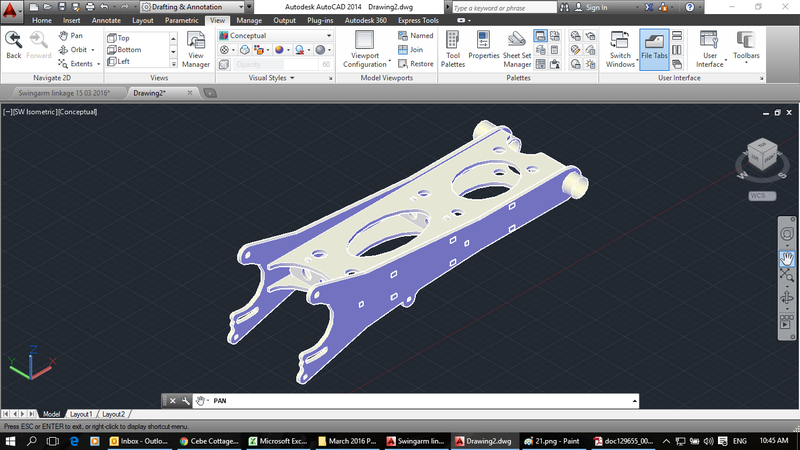
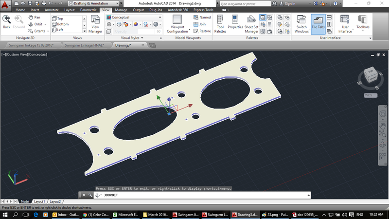
    My new design employs the use of flat steel plate rather than hollow tubing. The advantage of this is that you get away from 90° bends, which are inherent with square and rectangular tubing. I plan to use 6mm steel throughout, which will also allow for stronger welds without the risk of burning through as on tubing.

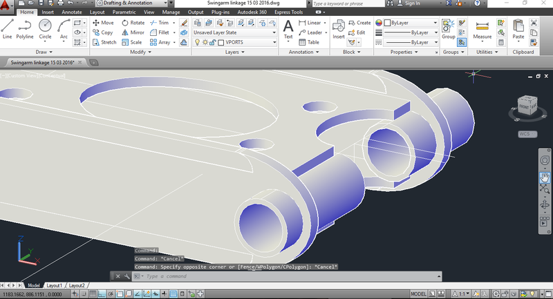
    I will have the front bearing tubes machined again, but this time, il keep them as one piece, joined together to make it easier to align when welding. Once welded, il just cut the joining bit out.

    Wheres the shock mount? I hear you ask...good question...the 450 linkage system attaches to the base of the bike frame, to a fixed point on the swingarm and to the bottom of the shock. As the base of the frame mount will be added and positioning of this is limited, and the bottom shock mount is located, well at the bottom of the shock, (which lies at a 70° angle) the variable is the point where the linkage attaches to the underside of the swingarm. This is then a simple case of finding the correct position for this once the swingarm is installed and the bike is set to the correct ride height. All i will do is weld a cross bracket with some ears on it in the correct position.

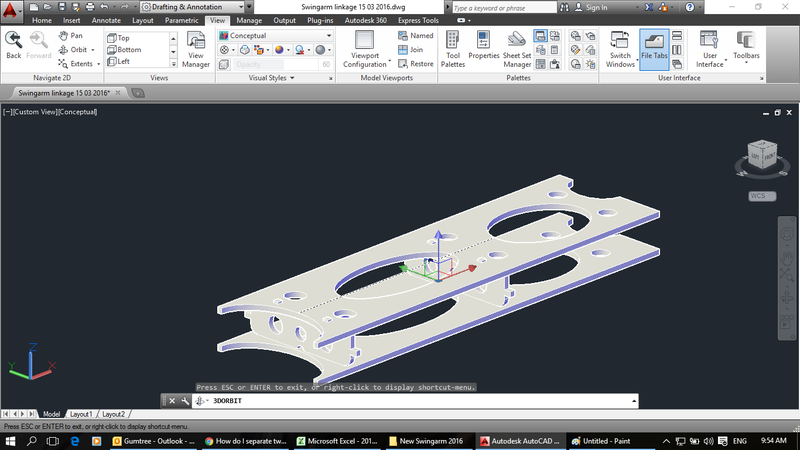
    I have allowed for the shock (Diam = 70mm) to pass through the swingarm through an ellipse of 90mmx 120mm. I have also used the 450 design to influence my cutouts, like the ellipse shape at the back for weight saving and more importantly, access to weld on the inside.

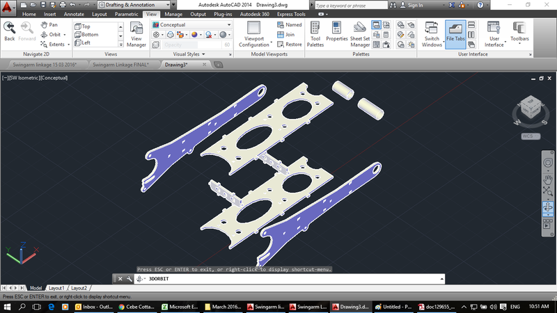
    I then decided, on the advise of a friend, the key the pieces, to allows them to "clip" together. This will aid assemble, eliminates the need for a jig and will give good weld point.

    A roundhouse carrier design went out the window with the Rand. Our currency has fallen badly recently and a billet carrier is just too expensive at this stage, plus, I snapped a piece of metal tubing while my carrier bolts and tensioner system was fine. Its obviously a tough system. Il try it again...

    I have sent the parts off, so I hope to have then back soon to get back on the trails again!

    There are a lot of construction lines in these pics, so dont worry about them. Please shout if you want a close up or different angle of any pieces.

    Il keep you all posted as we go.

    Once this is complete, Project WR200 is free to commence.

    Stay tuned...

    [​IMG]

    [​IMG]

    [​IMG]

    [​IMG]

    [​IMG]
     
  2. jbuckster07

    jbuckster07 Active Member

    Joined:
    Mar 20, 2011
    Messages:
    879
    Likes Received:
    264
    Trophy Points:
    115
    Occupation:
    Head Estimator/ Project Manager - Eclipse Co
    Location:
    Akron, Ohio
    TUNED IN! Love seeing this kind of stuff, keep us updated!
     
  3. Awk08

    Awk08 Administrator Staff Member Technician

    Joined:
    Jan 30, 2009
    Messages:
    24,427
    Likes Received:
    2,289
    Trophy Points:
    175
    I like it, tuned in !


    they way you designed it to "clip" together, shall we call it the Lego swinger ? :)

    ImgW.jpg
     
  4. Larry's Shee

    Larry's Shee Active Member Technician

    Joined:
    May 23, 2009
    Messages:
    9,271
    Likes Received:
    1,054
    Trophy Points:
    149
    Occupation:
    Unemployed carpenter
    Location:
    Ortskaville, MI
    You should have been a mechanical engineer instead of a geologist :p

    Would this be considered a monocoque design ?

    Continuous or skip/stich weld ?

    Brilliant design !! :cool:
     
  5. Fast6hand

    Fast6hand Active Member

    Joined:
    Oct 10, 2013
    Messages:
    2,022
    Likes Received:
    308
    Trophy Points:
    145
    Gender:
    Male
    Occupation:
    Audio and Electronics
    Location:
    West Palm Beach
    Roundhouse carrier possibly? Looks cool!
     
  6. jbuckster07

    jbuckster07 Active Member

    Joined:
    Mar 20, 2011
    Messages:
    879
    Likes Received:
    264
    Trophy Points:
    115
    Occupation:
    Head Estimator/ Project Manager - Eclipse Co
    Location:
    Akron, Ohio
    If I remember correctly reading through his other thread, since he lives in South Africa, paying for a billet carrier is outrageous in price due to money conversion. So he has to stay with the stock configuration.
     
  7. Blaner

    Blaner Your Friendly South African Ambassador

    Joined:
    Mar 26, 2008
    Messages:
    3,277
    Likes Received:
    183
    Trophy Points:
    114
    Gender:
    Male
    Occupation:
    Geologist
    Location:
    East London, South Africa
    Lego Swinger for sure! Indeed Larry, it would be a monocoque design. As for the roundhouse, I will just give it a bash again with the original setup. I did investigate a possible design, but the billet story is pricey. The exchange rate is a killer at the moment!

    I think by doing the lego design, half the work of setting it up for welding is done.

    Glad you all like. I actually did 2 years of Mechanical engineering, but all that mathematical theory was too much for me. Its a nice hobby now. Not to mention my AutoCad skills have greatly improved!

    The new setup should give around 10.1" of travel opposed to the stock 7.1" and my previous Honda 400ex at 9.1" :) The linkage system will also reduce the force exerted on the swinger as it acts at a more natural angle and a lot of movement is absorbed when the linkage works. The old blaster design with the shock at a flatter angle isn't exactly 1st prize.
     
  8. Blaner

    Blaner Your Friendly South African Ambassador

    Joined:
    Mar 26, 2008
    Messages:
    3,277
    Likes Received:
    183
    Trophy Points:
    114
    Gender:
    Male
    Occupation:
    Geologist
    Location:
    East London, South Africa
    News in is that I have picked up my laser cut swingarm components...all looks good! I had to pop around our company workshop for something so I got one of the guys to help me see if it would fit together. A little bit of tapping and filing later, we had a lego session and plugged it all together to creates a swingarm! ALMOST ready to go as it is!

    I had done some calculations based on the volume of the object from Autocad and it worked out that the whole thing would weight about 8.5kg. after plugging the parts together, it comes out at 8.2kg without any welds or front tubes. so total weight is looking at 8.5-8.7kg. Its on the upper scale of heavy but it will be strong!

    The dude had already started fitting it before I got a pic of the loose components, but here it is taking form in a test fit. Will get more pics later

    [​IMG]

    [​IMG]

    [​IMG]

    [​IMG]

    [​IMG]
     
    Blaster crazy, rshutchinson and Awk08 like this.
  9. Blaner

    Blaner Your Friendly South African Ambassador

    Joined:
    Mar 26, 2008
    Messages:
    3,277
    Likes Received:
    183
    Trophy Points:
    114
    Gender:
    Male
    Occupation:
    Geologist
    Location:
    East London, South Africa
    [​IMG]

    [​IMG]

    [​IMG]

    [​IMG]

    [​IMG]

    [​IMG]

    [​IMG]

    [​IMG]

    [​IMG]

    [​IMG]
     
    82cutty likes this.
  10. Larry's Shee

    Larry's Shee Active Member Technician

    Joined:
    May 23, 2009
    Messages:
    9,271
    Likes Received:
    1,054
    Trophy Points:
    149
    Occupation:
    Unemployed carpenter
    Location:
    Ortskaville, MI
    This is so ausome !!

    Finally came across something that is NOT on Google, weight of stock YFZ450 swingarm :(
    You know, little comparison :D
     
  11. Blaner

    Blaner Your Friendly South African Ambassador

    Joined:
    Mar 26, 2008
    Messages:
    3,277
    Likes Received:
    183
    Trophy Points:
    114
    Gender:
    Male
    Occupation:
    Geologist
    Location:
    East London, South Africa
    Would be a good comparison. No doubt mine will be a little heavier, although the 450 would use more material (aluminium) to make it stronger. I doubt il break this one, although Ive said that before and been horribly wrong...
     
  12. Larry's Shee

    Larry's Shee Active Member Technician

    Joined:
    May 23, 2009
    Messages:
    9,271
    Likes Received:
    1,054
    Trophy Points:
    149
    Occupation:
    Unemployed carpenter
    Location:
    Ortskaville, MI
    I wasn't going there. It looked good to me.

    What I did find was àftermarket arms were several pounds heavier.
     
  13. Awk08

    Awk08 Administrator Staff Member Technician

    Joined:
    Jan 30, 2009
    Messages:
    24,427
    Likes Received:
    2,289
    Trophy Points:
    175
    Lookin good Blaner !

    IF... a little weight gets added anywhere, over the rear tires is the place
     
  14. Blaster crazy

    Blaster crazy Member

    Joined:
    Dec 17, 2015
    Messages:
    572
    Likes Received:
    66
    Trophy Points:
    64
    Gender:
    Male
    Looking good
     
  15. Markblaster

    Markblaster Custom blaster

    Joined:
    Dec 6, 2015
    Messages:
    2,311
    Likes Received:
    760
    Trophy Points:
    175
    Love the CAD drawings and the work you have done. I remember doing parts like this that slot into each other of a buggy I did. Keeping a eye on this build.
     
  16. Blaner

    Blaner Your Friendly South African Ambassador

    Joined:
    Mar 26, 2008
    Messages:
    3,277
    Likes Received:
    183
    Trophy Points:
    114
    Gender:
    Male
    Occupation:
    Geologist
    Location:
    East London, South Africa
    I have dropped the pre-assembled swinger with a friend who is going to turn the front tubes and bearing inner tubes. He is also going to get it to work with a set of needle rollers again. Last time I used bushes, which worked well, but rollers are obviously 1st prize.

    After that its a small matter of welding it up, setting it on the bike and then finding the point where the rear linkage must fit by setting the ride height. Il also have to mount the linkage setup onto the back of the frame.

    Any ideas on what type fo welding to use here? CO2, Arc, Mig?

    But first, my 400ex shock bushes at the top shock mount have siezed fast...need to get that off!
     
  17. gsustaitav19822

    gsustaitav19822 Member

    Joined:
    May 26, 2013
    Messages:
    179
    Likes Received:
    52
    Trophy Points:
    79
    Gender:
    Male
    Location:
    immokalee fl
    i would go for mig
    just put down some nice neads with some.035 solid wire and 75/25 shielding gas
     
  18. Herpderplol

    Herpderplol BRRAAAAAAAAAPP

    Joined:
    Aug 22, 2012
    Messages:
    6,290
    Likes Received:
    496
    Trophy Points:
    136
    Gender:
    Male
    Occupation:
    Spending Money
    Location:
    Dickinson, ND
    Because of how it is being welded together, arc and MIG will virtually end with the same results, just which are you more experience in.
    Also look at the inside welds and see how you cane get a rod vs. MIG gun inside of it
     
  19. Herpderplol

    Herpderplol BRRAAAAAAAAAPP

    Joined:
    Aug 22, 2012
    Messages:
    6,290
    Likes Received:
    496
    Trophy Points:
    136
    Gender:
    Male
    Occupation:
    Spending Money
    Location:
    Dickinson, ND
    Also one thing I was wondering, and i think i know the answer to the question but im still going to ask.

    Did you consider placing a bend where I put the green Line, and following up the red line?
    Leaving the same space to weld as further forward on the design

    My guess is you were avoiding the bends in the design, not to mention it would be semi-challenging to get an exact bend possibly?
    I'm just poking at the cosmetic/OCD side of my brain :p
    swinger.jpg
     
  20. Blaner

    Blaner Your Friendly South African Ambassador

    Joined:
    Mar 26, 2008
    Messages:
    3,277
    Likes Received:
    183
    Trophy Points:
    114
    Gender:
    Male
    Occupation:
    Geologist
    Location:
    East London, South Africa
    0
    Good point, i never really considered that. The only really complications with that would be as you say, 1.) getting the bend accurate. 2.) Bending would weaken the material. 3.) You would have a wider cross member at the back thereby adding more weight. All knit picky points, and your idea is something I may have used if I had thought of it!!

    In all honesty, what i found during thinking of designs for this, is that there are a million ways to build a swingarm. I went through a few ideas, most of which i will list here to maybe pick some interest.
    1. Rectangular tubing with thicker walled tube as done previously (doomed to fail)
    2. Angle iron frame construction (Cosmetically bad)
    3. CNC solid block aluminium design a-la-YFZ style (Veeery pricy)
    4. Laser cut aluminium plates bolted together with shear bolts. (allows flex and friction between plates and points to shear if the stress is too much.) threw this idea away, but its an interesting one...
    5. Rectangular tubing with laser cut 6mm reinforcing plates (A compromise between the monocoque design i settled on and the original idea)
    6. Aluminium monocoque design as I am doing with ??mm plate.( Unsure of strength capacity here, also unsure of how thick it would need to be)
    7. Chromoly everything - cant seem to get hold of this stuff here, well not for less than an artificial limb.
    8. Stainless steel everything. (Too brittle - flexibility is required.)
    I had to look for something that would be more or less lightweight, simple to build, had as few seperate parts as possible and will be strong enough. This design has only 8 loose parts, including the front tubes, is locked in square before you weld, eliminating the need for a jig and all those alignment issues while being strong enough (I hope) and hopefully light enough.
     

Share This Page