Porting 101

:confused:
Actually typed that reply like two days ago, but didn't hit post LOL

Read that linc for Banshee porting, and got to thinking about effects of stroker crank.
Crankcase volume is increased due to piston traveling further up, thus taking in more A/F. And seeing as piston will travel further down equal amount, it should compress it more, increasing velocities at trans openings.
 
Preaching to the choir? You don't have to tell me lol. Every other time that topic has arisen, it's always included the topic of DIY vs. professional porting. I got pretty mad at ZillaFreak over there.

I know that there are a lot of guys who know a lot that just don't feel like posting, both here and there. I agree on the knife edge divider on the piston ports, but that's about the only place. I've since been on another Blaster that was ported in a very similar fashion to the job I did on the wife's, and it had a bit wider powerband. I think that has a lot to do with the port tunnel geometry at the bottom since mine is more rounded with a knife edge divider and his was more of a straight shot with a round divider.

I'll have to do some more work there when I get the chance. I wish I had a good grasp on figuring boost port rood angles...
 
I still need to get my grinder back from my buddy. He's been holding on to it for a bit longer than he needed, but I'm only doing minimal work for now, so I can deal with not having it. I'll get you some pics when I get them back.
 
Psssh, usually they post a pic of some hacked LT250/500 jug that HAS to be a joke, (Stevie Wonder/Helen Keller port work :eek:)

What do they think happen in 1987?
And yet to see any "pros" admit mistakes/failures :rolleyes:
 
Psssh, usually they post a pic of some hacked LT250/500 jug that HAS to be a joke, (Stevie Wonder/Helen Keller port work :eek:)

What do they think happen in 1987?
And yet to see any "pros" admit mistakes/failures :rolleyes:

I did see Arlan Lehman say that he's screwed a few jugs up in the past lol. It was a comment on a picture of a jug from CT racing. The owner sent the jug to be ported and when he got it back, he got a fully ported cylinder and only then did he discover the crack. They still charged him and claimed a cold seizure was the culprit, even though he hadn't even installed it yet.

I know my LT250R jug was a mess after I got done :oops:. I had to take it to a local builder to get it fixed. I went back in later and opened it up a lot more.
 
I'll be adding to this thread tomorrow night. I've ported 9 cylinders and 3 heads since the last post on here and I'm mapping the 10th one now. KX85 w/PV. Given free reign to do whatever I want.

I'll do a write up with pics on how I've come to do my work.

Really quick, I found that 186 exh, 128 mains, 128 secondaries, 126 boost port made a good bit of very useable power on the 250R that I ported. Lots of snap, good bottom-midrange, excellent upper midrange and top end, pretty good over-rev.

MacDizzy's posted numbers were 188, 132, 130, 128 and he has a wide powerband with more upper midrange.

This leads into port duration considerations. Shorter transfers in relation to the exhaust will create tons of peak power and cut power above and below the curve. This is almost entirely true for all applications, but the specific numbers for each configuration very quite a bit with each application.

The Banshee that I ported used 192, 132, 130, 130 with flat top ports. This made for a good upper range build which paired nicely with the CPI pipes.

Compared to the 250R, the Banshee had shorter transfers in relation to the exhaust port. However, the 250R has a divider between the exhaust ports and can go to a much wider port. As a result, the decreased blowdown isn't as much of an issue since pressure bleeds faster with a larger port.
 
Pt. 3

Alterations: Durations and area

-BE CONSERVATIVE

Let me state this before you read any further. Every builder has a method and a set of numbers they like to see. I got my start by looking at the numbers that others tried and their results. I then modified them to fit my style of porting and though I don't recommend you take anything I have to say as a rule of thumb, this is the way that I've come to find great results for myself. I was very fortunate to have a multiple world record holding builder take me under his wing. Am I as good as KOR, LED, or Flotek? No, but I'm happy with what I can do (as are a few others :D)

I always start designing my ports with the exhaust port height. Most exhaust ports are close to 178-182 degrees of exhaust port duration. If I need more top end power, raising the exhaust port will generally shift the powerband to the right. Too much duration will make your powerband peaky. This is in part because of the height difference between the exhaust and the transfers and boost port. I generally widen the exhaust port to around 2-3mm of clearance between the exhaust port and the exhaust side of the mains. I try to keep all of my corners somewhat rounded unless I don't want to increase duration or if I'm getting too close to the mains. In this case, I'll reduce the radius on the corners just a little. A short life, all out screamer will typically have square ports with a 1mm radius or less on every corner.

If you're working on a bridged exhaust port, be cognizant of your bridge. If you narrow it too much, you'll reduce the ability of it to shed heat to the surrounding area. This will cause it to bulge into your piston. After honing the cylinder, I like to take 180 grit sand paper to the cylinder on the bridge just for a few seconds to remove enough material to compensate. Again, reducing the radii on the bridge can reduce the ability to shed heat. Be conservative.

Blowdown is the time between exhaust opening and transfer opening measured in degrees. I prefer around 28-31 degrees, but don't take that as the golden rule; that's what I like to see. This means that if I have 180 degrees of exhaust duration, I'd like to have 118-124 degrees of transfer timing for a blowdown within my range. Old Suzuki and Yamaha bikes had huge blowdown periods and had gobs of peak power but no power above and below peak. Less blowdown GENERALLY means a wider powerband TO AN EXTENT. Too short and peak power will suffer and over-rev will vanish.

After I have my exhaust duration, I can look at what I want for transfer duration. Say I go with 188 degrees and I want to raise my transfer ports. If I read 132 degrees on my timing wheel, I'll have 28 degrees of blowdown. This puts it within the range that I LIKE TO SEE. If my transfers are at 132, I'll be happy with anywhere from 188-194 degrees of exhaust duration.

Now as stated above, I start with exhaust. After I get that figure and determine whether my transfer ports are within my blowdown preference range, I look at width. My rule for width loosely considers Gordon Jennings's Port-Time Area (PTA) concept. I prefer this a bit more:(http://www.dragonfly75.com/motorbike/formulas.html), but still, this is a loose consideration of mine. My largest factor here is the port shape from bottom to top. If I need to grind the cylinder back some to allow for the shape I'm after, I'll reference PTA to ensure that I'm within the limits before I cut.

Staggering the port durations can assist in power spread. If performed improperly, it can ruin the engine (like everything else to do with porting). I don't have very much experience here, but I've seen it done and it does work. I've never seen a difference in staggering of more than 2 total degrees. IIRC, the example that comes to mind is 188 exhaust, 130 main, 132 secondary, 130 boost. Don't go too radical here.


Alterations: shaping

Now, I like to aim my ports as much as possible to the rear of the cylinder. This is for a few reasons. Once all of the AFM piles up at the back of the cylinder, the boost port will help push it upward, purging the cylinder further. Yes, the expansion chamber does the suck and blow thing (haha), but it really blows more below the powerband and sucks too much in over-rev. Aiming the ports rearward will help with filling the cylinder with more AFM and less exhaust (remember the first paragraph?). This will broaden your powerband. From my experience, this doesn't really affect peak power that much, but it does affect power delivery everywhere else. As for grinding, this may mean removing some material to allow the port to aim the charge in a more desirable path. For you first timers, this can also mean not cutting that one part down to give you that ever so perfect flow divider from some sh*t you saw in a NASA picture. Sometimes, leaving an area alone can allow it to function much better in conjunction with other areas. This goes back to "be conservative".

Now if you consider this for a minute, you'll appreciate an extensive port job much more. If you cut a hole in a piece of paper and blow through it, how well does that path of hot breath stay together and pile up? Not well, huh? Now if you take a piece of tubing and blow through it, you can see that it focuses the path much more effectively. This is why ports that are flatter as a whole while entering the cylinder have more velocity and a wider powerband in general. This takes serious time in most cases.

MacDizzy mentioned this quite a few times on his site. I've also seen a few applications where the outside of the ports were cut through entirely and epoxied over just to accomplish this. From what I've seen, it does work well. The preferred way is to add material to the inside radius and remove from the outside before merging into a flat port.

Now the roof angle matters as well. An angle of 5 degrees on the roof can make a noticeable difference in some applications. I prefer 0-5 degrees on the transfer roofs. A flat roof will contribute more to peak power at higher RPM, while a 3-4 degree roof will spread the power around some. As for the boost port, I've never tried much, but I've never had a reason to. They work just fine like they are stock for me with just port-matching the sleeve to the cylinder. The largest reason that I don't have much experience with boost ports is because I haven't done very much to them before. Maybe KOR or someone else can chime in here.

Lastly, bevel all of your ports. A .5-1mm wide bevel that's .2-.5mm deep has always sufficed for me. Being a little generous with the exhaust bevel is fine.


Side notes:

No explanation as to why, but the builder who taught me said, "no knife edges except occasionally". Sadly, he hasn't explained what fell into the occasionally category quite yet.

Keep structural integrity in mind.

Lots of small changes equals one big change

It's a lot easier to not cut something than it is to put it back. Be conservative.

80-180 grit in a perpendicular direction to travel is great. I always mirror polish my exhaust because I have time 9/10. Otherwise, a 200 grit finish is more than enough.

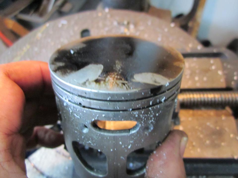
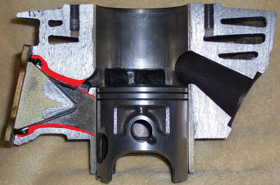
If you see carbon buildup in the exhaust, flow probably isn't doing too well in that spot.

Power hides within the design of the transfers

If nothing else, remember these 3 things: Be conservative, take your time, don't try to make your tools do something that you can't make them do/they shouldn't do.


I know I missed a lot, but with as much as I wrote, I'm sure there were some typos and holes in explanation.[/QUOTE
 
I am currently making some mods to my blaster I like your article. I am trying to use a mix of ken o,connor and the mc dizzy web site but considering I have raised my exhaust port about a 1mm or 1.25mm raising the cylinder as mc dizzy article states my exhaust numbers are different he states 88.5 opening with 1mm and 2 gaskets. my reads 86 degrees ex. opening with 2 gaskets. I was going this direction as to gain some transfer port duration with out have the tools to do that. I am also going to reshape head and cut to 17cc. I have 30mm carb. and a fatty pipe. anybody have any thoughts or suggestions?
 
Hey Best, why don't you chime in? I know you have some good info, I've seen it.

Well, first off, the Blaster is a wonderful engine to learn on. Simple and quick to disassemble/assemble.
Second, if you just follow the leader to a maximum port job you will learn nothing.
Knowledge is built step by step, so like you said: :"BE CONSERVATIVE" and go one step at a time.
Make a small change, put the engine back together and run it (the "Butt Dyno"). Did it improve?

For example: How high to cut the exhaust port roof for max power?
Problem: Once cut too far the roof cannot be easily repaired, so how to know best result?
Solution: Cut a 1mm relief at the exhaust port on an old piston (see Vitos example):
vitos_piston_kit_blaster.jpg

and test roof cuts less than 1mm at a time, assembling and testing each time until power peaks.
Putting a stock piston back in will let you get back to the ideal port timing.
You now know the best height for your present pipe/intake/head/carb/etc combo.

An old "last bore size" cylinder can be a great learning tool while it still runs, loose as it may be.
Make the intake a little larger, assemble it, does it run better? Try a little larger until it peaks.
Now, try the exhaust. Does larger make more power?
Here was a test my son and I did on a well worn piston for an extra port:
546193_10151385060685803_1608828949_n.jpg


540904_10151385060825803_967330345_n.jpg


406043_10151385061070803_205544193_n.jpg


It worked pretty darned good when we got it to here!
So let's not stop there:
388320_10151390038075803_72962053_n.jpg


Worked better, keep going:
249934_10151390023775803_769678058_n.jpg

(Weird, no drill holes in the vise. Only a machinist would have a drill press vise like that)

Not so good, but lets not stop:
538647_10151390024080803_835676392_n.jpg


As neat as this extra port may look, it was a dud compared to the 6mm x 19mm slot, which worked well.
We learned something. Appearances do not make speed. More is not always better.

Be conservative, modify in single small steps and butt dyno in between steps to learn what works and what doesn't.

Steve
 
Is your goal to learn or just build something faster this once? I can post pictures of a somewhat fast port, whereas the learning process takes much, much more time (and is more fun).

The most important thing that I've learned since my last few posts here is that the design of the transfers is key. You can get by with some good duration numbers and a decent exhaust shape, but the shape of the transfers holds the power.

At this point, I'm pondering the ability of the transfers to maintain velocity vs. their ability to hold as much AFM as possible so that more is instantly available when the piston uncovers them. The AFM has to travel in some weird ways to get there.

I've tried to bring the opening and exits of the ports to the rear as much as possible in an attempt to allow more mixture to flow straight in AND to aim the charge rearward. Boyesen ports can aid in transfer feeding, but need to flow with the rest of the cylinder. I disagree with feeding them almost 120° away from the direction of the transfer flow like a lot of builders that use them, but I do think that they have an idea hidden within an idea. Aiming the Boyesens and shaping them correctly is just as important as their size. Trying to get them to feed the mixture right onto the transfer divider is my goal and it's worked well for me.

I've never been able to find much power on the intakes. Maybe I'm doing it wrong, but I've yet to see a great design pop up without using Best's method. I've got a few boost port ideas from the last time, but that's about it. Even then, it basically amounts to creating as much of a venturi stack shape as possible. I still haven't tried to develop a boost port shape.
 
<SOME SNIPPED>
I've never been able to find much power on the intakes. Maybe I'm doing it wrong, but I've yet to see a great design pop up without using Best's method. <MORE SNIPPED>

I presume you are talking about the epoxy filled reed box?
The extra slot in the piston is a small gain, the epoxy filled reedbox is a big gain.

252249_10151325140485803_804954678_n.jpg


27894_10151362954045803_1391383925_n.jpg


The whole point of this is to keep the intake cross-sectional area close to constant or maybe funneled a bit to keep velocity up for flow momentum and to keep fuel from dropping out. It also keeps crankcase compression up.

Steve
 
I need to try the epoxied intake. It makes so much sense, but I wonder what I could improve upon over your design. Any thoughts?

I'd do it up in COMSOL, but I'm nowhere near good enough with fluid dynamics to create a functional model of a 2 stroke.
 
I have done the Epoxy in the intake as well as a small amount of epoxy in the cases where the cylinder meets with the cases. (to lower ccv) I didn't add the amount of epoxy Best did but I did add some. As far as for the epoxy in the intake I did notice a much better throttle response along with a smoother running engine all through the power band. Also a smoother "hit" in the power band you might say in the top end that came on earlier but smoother. All in all I guess you would say better mid range pulling through the top end.

I was also running a reed spacer between the cyl and the reeds. I also epoxied the void in the cyl where the reeds and bolts used to go all the way back to the reed block itself. Also on each side there is a void where I filled with epoxy also. Next time I have this motor apart I will take some pics.
 
I need to try the epoxied intake. It makes so much sense, but I wonder what I could improve upon over your design. Any thoughts?

I'd do it up in COMSOL, but I'm nowhere near good enough with fluid dynamics to create a functional model of a 2 stroke.

Considering this engine has the off-idle torque of a big bore stroker (no throttle needed, release the clutch, it won't stall), has the powerband kick in early and pull hard to 9000 rpm, I'd say there is not a lot of improvement needed. You could be a bit more bold in opening up the intake port sides, but I wanted longevity also, and I was starting with a worn out high clearance piston/cylinder. JoeAK47's porting made more ultimate power and reved higher but did not have the low and mid-range by a small amount. I thought of epoxying Joe's cylinder intake but his handiwork is so beautiful, it would be like putting a plastic arm on the Venus d'Milo!

Steve Best
 
I'd like to think that I've made quite a bit of progress with porting since I started this thread. I have a few discussion topics that I'd like to bring up. Hopefully, we can get some more in-depth discussion going.

Boyesen ports

The subject is pretty lacking if you research it IMO. Everyone seems to love them or have no use for them. However, on applications that have them stock, I have noticed that the vertical angle at which they feed the secondaries seems to be largely determined by the intended RPM range. 2 different year KX85s had Boyesens that were pretty flat (appx. 30° roof and 10° floor if memory serves) whereas the different CR and TRX 250s that I've been in have much steeper angles.

I think this has a bit to do with where the charge that flows through them ends up with the time they are allotted. Rephrased: higher RPM wouldn't allow much time to pull the charge down and would allow it to just shoot right to the port divider to evenly feed the ports, whereas a lower RPM application would have Boyesens that had more sufficient time to get the charge below the port divider before the transfers opened. This reverse engineered picture is my mind's eye, but relevant IMO.

I also think that the size of the Boyesens may be partially determined by the crankcase compression. Larger Boyesens wouldn't build enough velocity to prevent reversion when the piston travels downward. It would feed the boost port on the down-stroke for sure, but the largest issue that I see is that they would (in a backward flowing state) flow directly to the side of the reed, not doing as much to close them. This is why I believe that one of the primary reasons that most are tapered from intake to transfer is to prevent reversion, as well as to get a good bit of velocity up to shoot the charge across the transfer divider.

On the other hand, this may all be false and the shape is dictated by smooth flow from the intake sides and structural integrity, which are obviously important. Nonetheless, I think if there is at least some room for improvement, it should be chased.


Secondary kicker

I've noticed in all but one of the cylinders that I've been in have had either a dip or sleeve kicker where the port would otherwise continue nearly tot he boost port. The only one was a KX85 that didn't have them from the factory. I think that the primary goal is to affect flow at different RPM. The kicker would help keep the charge from cutting the boost port off at low RPM, but the dip would be overshot entirely at higher RPM. I haven't tested this particular area, but I have done some unrelated CFD testing that makes me think that the kicker would allow the charge to almost swirl up the rear of the cylinder given the short time that they're open.

Ont he other hand, I can see where the dip would create a low pressure spot and only really allow maximum flow across the exhaust side of the secondary while also helping pull the charge rearward due to the pressure differential. I shall epoxy a test cylinder when I get my hands on another one to test them back-to-back.


Intakes

I've seen thousands of intake designs from KOR's to HJR and they all differ wildly. I wonder if the relationships are inter grated or if theory is all that is relied upon. I'm not sure, but I'm positive there is a relationship between the intake size and dimensions and the shapes of the transfers.

I have implemented the way the KX cylinders have a rounded tunnel that extends along the edge of the reed petals to take advantage of the AFM that comes out the sides of the reeds while open and have had some success in making a bit more upper midrange and top end power at no expense to bottom end. Epoxy was used to fill the area just beside the reed cage in so as to increase crankcase compression.


Boost port

RDZ had an excellent idea in theory for feeding the boost port, but it didn't last long at all. He basically cut from the boost port down to the sleeve and down to the intake windows. This allows a straight shot upward and is very similar to the recent high=performance cylinders offered for a banshee.

More to come, pending discussion...
 
Epoxying the "kicker" on the secondary has been done and I remember reading that there was NO improvement anywhere and power was actually lost at ALL rpm. Don't remember who wrote it or where I read it but do remember reading it.
 
That makes me wonder how close the stock kicker is to the optimal dimensions... I'd imagine that if there is any gain to be had, it would be rather difficult to find.
 
If going with larger Boyesens (if you can fit them that is) and worrying about gaining ccv, there are plenty of places that can be epoxied to make up for it. Even in the cases themselves.


Take away here add there. Imo it is the small intake that limits these cylinders.