So, you’ve got your hands on a set of extra HP fully adjustable A-arms for your Blaster and im sure you are very excited and keen to bolt them all up and go churn some mud, many may do just this without considering - or if you got that far, without understanding what the “fully adjustable” part of your new bits actually means, I will do my best to explain some basic suspension dynamics and how you may adjust them in order to achieve optimal settings and use out your front end.
If you are reading this and thinking “Mmm, better get cracking and setup my stock Blaster!” I regret to tell you that the stock blaster front end is not “fully” adjustable and only has two avenues of adjustment, whereas a set of ASR, Houser etc with Elka etc shock can provide you with up to six different dynamics to set.
These six settings are: Caster, Camber, Toe, Shock Spring Tension, Shock Compression and Shock Rebound. Of these. I will attempt to deal with setting your caster, camber and toe.
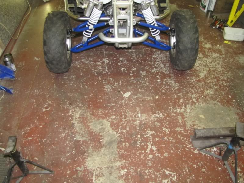
I will be using a set of what looks to be +2 Full Flight A-arms for a YFZ450 with YFZ450 shocks.
Lets start with a brief rundown of what these three terms mean:
CASTER:
Caster is the amount of angle that the spindle has in relation to the vertical centre line of the wheel.
If the upper ball joint is further forward than the lower ball joint, it is said to have negative caster. If the upper ball joint is further to the back than the lower ball joint, it is said to have positive caster. The greater the amount of positive caster, the more stable the ATV will be at speed. The less positive caster it has, the easier it will steer and the quicker it will turn. As the spindle is laid back, the tire has to lie over more when the front tires are turned- (much like a Mercedes Benz when they are parked with the wheels at full lock…ever noticed?) This adds stability. If there is not much angle, the wheel will turn more easily, making it quicker and easier to turn.
Now Blaaster was kind enough to suggest that the stock Blaster caster is set at 9 degrees, this is not adjustable on a stock Blaster as this measurement is built into the frame by way of A-arm mounting positions.
Lonestar Racing suggests these settings for Caster:
Motocross: 5 -7 degree
Cross Country: 5 – 7 degree
Sand Duning: 3 – 5 degree
Desert Racing: 6 – 8 degree
Recreational: 5 – 7 degree
Perhaps Yamaha set the Blaster caster at 9 degrees to make it more stable and controllable for beginner riders as it was an entry level bike… this makes sense when you consider how heavy your steering gets when you add front spacers or flip your front rims.
CAMBER:
Camber is the amount of degrees that the tire and wheel is tilted in or out at the top in relation to the bottom of the tire.
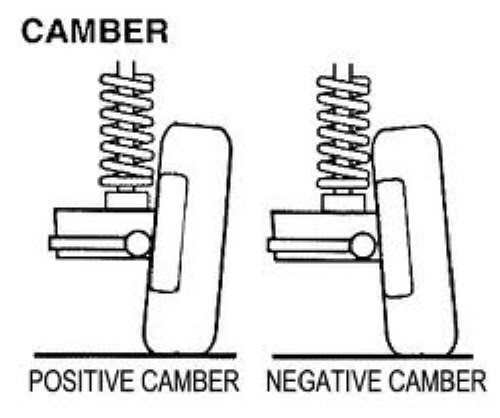
A tire that is tilted in at the top and out at the bottom is said to have negative camber. The further it angles out at the bottom the greater the amount of negative camber.
For positive camber, the top of the tire is further out than the bottom. The reason for having camber in your front end is because your suspension is forced over in a corner and in doing so, the suspension flexes. With everything in motion, all this force wants to flex the tire more upright, or reducing the amount of negative camber.
A tires greatest traction is achieved when more of the tread is in contact with the ground. As the bike enters a corner, the forces tend to bend everything over, adding positive camber. To make sure that the tires greatest amount of tread is in full contact when it is most needed, we set up the front suspension with a negative camber.
Again on a stock blaster your camber is not adjustable!
Lonestar Racing recommends the following camber settings:
Motocross: 1 -3 degree
Cross Country: 1 – 3 degree
Sand Duning: 2 – 4 degree
Desert Racing: 2 – 4 degree
Recreational: 1 – 3 degree
TOE:
The toe of an ATV measures the relation of the leading edge of the front tires to the back of the tires. Toe-out refers to the fact that the front of the tires point out. Toe-in refers to the fact that the front of the tires point in.
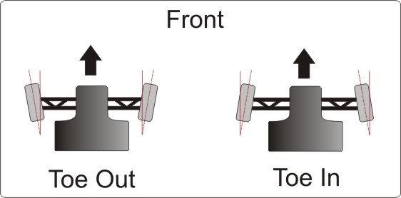
Mostly, the recommend setting of your toe-in is ¼ of an inch.
Now you are able to set your Toe on your stock Blaster!
Now that we have established what is what, we need to learn how to set all of this up accurately and symmetrically.
Before you start, you need to check a few things and make your sure you have all the tools you will need. To start with find yourself a garage or level paved surface, then find a spirit level (bubble level) about 1m long and check the levelness of your chosen surface, you may notice a slight gradient in the case of a garage, this is to allow for water to run out the door and not into the corners, bear this slight angle in mind, although it shouldn’t play a huge role.
Next, make sure all your tire pressures are equal, set your tires just a little above what you normally ride with them at. It is important to remember that while you may need a stand or a jack to get the wheels off and make adjustments, it is vital to replace them and let the bike stand on its wheels when checking the measurements
Other tools you will need include all your necessary spanners, a shorter 500mm spirit level and ideally an angle finder (contractors protractor) or a clinometer, I was lucky enough to have a Brunton geological compass on hand which incidently is able to measure angles by using a small bubble level and a clinometer built in to it. You will also need a steel ruler, a tape measure and a few other goodies like a notebook, pen and a permanent marker.
Your first port of call when setting up is your caster, followed by the camber and lastly, the toe.
SETTING CASTER:
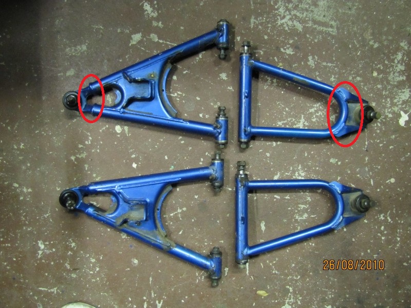
My A-arms utilize heim joints on the upper A-arms which allow for the adjustment of the top A-arm and setting of the caster, some others do not use this system and instead employ a shim system, regardless of which, the measuring of the caster is exactly the same for both, since I have heim joints, I will be explaining this method.
When you get your top A-arms the first step is to screw in the heim joints all the way, once you have them all in, line them up by ignoring half a turn or so in order to get both joints located on the same axis so a bolt can pass through them. Get a permanent marker and make a mark on the top side of the arm and on the heim joint so you know which way is up and so you can count the turns.
here you can see my upper heim joints:
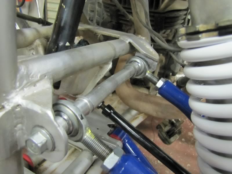
In order to get your top ball joint behind the back one, you sort of need to twist the arm by turning out only one of the joints, to push the ball joint back, you need to turn the back heim joint OUT, start with 3 complete (360*) turns and leave the front heim at 0 turns, It is handy to have a notebook on hand and keep track of these turns!
Adjusting the heim joints requires you to remove the arm each time and turn the joints, this is a mission but its part of the deal…
Ok so once you have set them as mentioned, assemble the arm, put the wheels back on and let the bike stand on the ground, you may at this point want to simulate rider sag by measuring how much suspension travel you have when you are on the bike and use ratchet tie downs to compress the suspension to the measurement, I for one didn’t find this too necessary because the caster does not change through suspension travel, what is important however is frame angle, if the back is lower than the front, it pushes the bottom ball joint further forward and pulls the top ball joint backwards thus giving more caster than when level, and vice versa for the front end, however in reality, with riding, generally, both front and back will compress at a similar time such as hitting a ditch etc, and although this is very simplified, including suspension travel dynamics will make things VERY complex, for example, do the left and right front suspensions move exactly the same in real life conditions? Not likely and so to keep it simple, I ignored suspension travel, it is important to have the tires on in order to get the basic frame angle right, if you put the front on a stand and lift it up, you are simulating back end compression and thus measuring and setting it up like this will give you false readings.
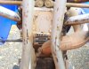
Ok, so you have 3 turns on the back upper heim joint and 0 on the front, now turn the wheel you are working on the extreme outer limit of its turn and grab your 1m level, position it against the bottom ball joint thread and against the top ball joint thread. If the top of the straight edge leans towards the rear of your quad, you have positive caster. This is what you want. Rest the angle finder on the edge of the straight edge. This will tell you the exact caster setting. You may need to adjust the Heim Joints by turning one in or out more than the other to get the appropriate setting. In my case I used my compass as so…
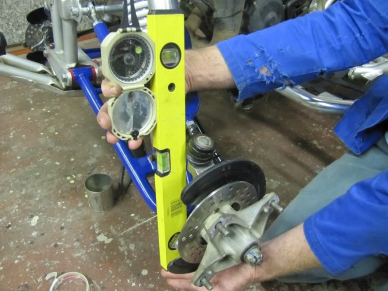
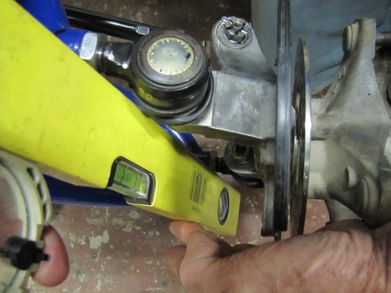
Do this for each wheel and make sure they are both the same, I had an issue with the front leg of the upper A-arm hitting my spring and so can only achieve 3.5 degrees of caster before I hit the spring.
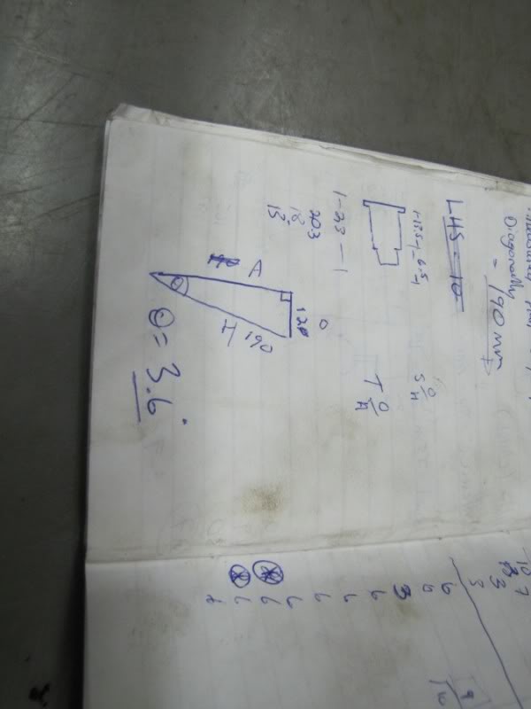
Once you have a degree measured and set, you can double check this using god old trigonometry! To do this, measure the distance between the thread of the ball joints, mine turned out to be 190mm, then place your level against the bottom thread and lean it away from the top thread until the level is perfectly level, then measure with a ruler the distance between the edge of the upper ball joint thread and the edge of the level. Mine turned out at 12mm.
Once you have these two measurements, you can do a simple trig calculation to work out the angle, I am looking for angle theta and so use sine-1 = Opposite/hypotenuse to work out the angle of caster, in my case my calculations matched my measurements. sine-1 = 12/190 = 3.6 degrees
SETTING CAMBER:
It is important to note that you shouldn’t set your camber until you have set your caster, this is because with the heim joints, screwing the joints in or out directly affects your camber as well as your caster and so it is best to set your caster and then fix up the camber afterwards using the threaded ball joints.
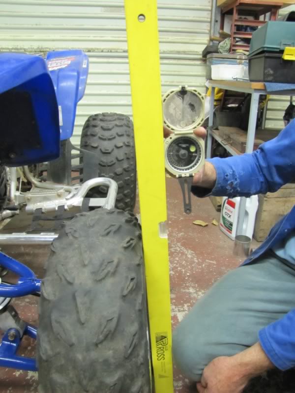
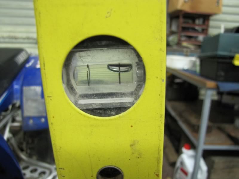
Setting the camber is a much easier process. Rest the straight edge of the level against the outside of your front tire (making sure both wheels are pointing straight and you are touching the same part of the tire, top and bottom). The top of the level should lean inward for negative camber. Now put the angle finder against the straight edge and note the reading. If you need more or less camber than you want or need, you are going to have to remove one of the ball joints in order to adjust it. First remove the split pin and castle nut off of the ball joint, then “smack” the side of the spindle right where the ball joint goes through the spindle to jar the ball joint loose. It will take some pressure to remove it, and it helps if you lift up on the arm itself as your hitting the spindle. For more negative camber, turn the upper ball joint into the a-arm (clockwise). Reassemble and recheck, I got mine in at 3 degrees which looks purposeful")
If you are reading this and thinking “Mmm, better get cracking and setup my stock Blaster!” I regret to tell you that the stock blaster front end is not “fully” adjustable and only has two avenues of adjustment, whereas a set of ASR, Houser etc with Elka etc shock can provide you with up to six different dynamics to set.
These six settings are: Caster, Camber, Toe, Shock Spring Tension, Shock Compression and Shock Rebound. Of these. I will attempt to deal with setting your caster, camber and toe.
I will be using a set of what looks to be +2 Full Flight A-arms for a YFZ450 with YFZ450 shocks.
Lets start with a brief rundown of what these three terms mean:
CASTER:
Caster is the amount of angle that the spindle has in relation to the vertical centre line of the wheel.
If the upper ball joint is further forward than the lower ball joint, it is said to have negative caster. If the upper ball joint is further to the back than the lower ball joint, it is said to have positive caster. The greater the amount of positive caster, the more stable the ATV will be at speed. The less positive caster it has, the easier it will steer and the quicker it will turn. As the spindle is laid back, the tire has to lie over more when the front tires are turned- (much like a Mercedes Benz when they are parked with the wheels at full lock…ever noticed?) This adds stability. If there is not much angle, the wheel will turn more easily, making it quicker and easier to turn.
Now Blaaster was kind enough to suggest that the stock Blaster caster is set at 9 degrees, this is not adjustable on a stock Blaster as this measurement is built into the frame by way of A-arm mounting positions.
Lonestar Racing suggests these settings for Caster:
Motocross: 5 -7 degree
Cross Country: 5 – 7 degree
Sand Duning: 3 – 5 degree
Desert Racing: 6 – 8 degree
Recreational: 5 – 7 degree
Perhaps Yamaha set the Blaster caster at 9 degrees to make it more stable and controllable for beginner riders as it was an entry level bike… this makes sense when you consider how heavy your steering gets when you add front spacers or flip your front rims.
CAMBER:
Camber is the amount of degrees that the tire and wheel is tilted in or out at the top in relation to the bottom of the tire.
A tire that is tilted in at the top and out at the bottom is said to have negative camber. The further it angles out at the bottom the greater the amount of negative camber.
For positive camber, the top of the tire is further out than the bottom. The reason for having camber in your front end is because your suspension is forced over in a corner and in doing so, the suspension flexes. With everything in motion, all this force wants to flex the tire more upright, or reducing the amount of negative camber.
A tires greatest traction is achieved when more of the tread is in contact with the ground. As the bike enters a corner, the forces tend to bend everything over, adding positive camber. To make sure that the tires greatest amount of tread is in full contact when it is most needed, we set up the front suspension with a negative camber.
Again on a stock blaster your camber is not adjustable!
Lonestar Racing recommends the following camber settings:
Motocross: 1 -3 degree
Cross Country: 1 – 3 degree
Sand Duning: 2 – 4 degree
Desert Racing: 2 – 4 degree
Recreational: 1 – 3 degree
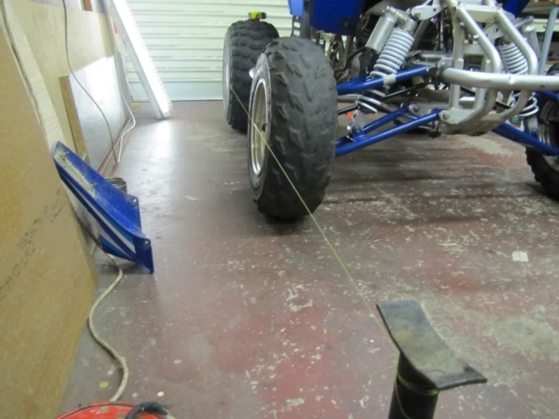
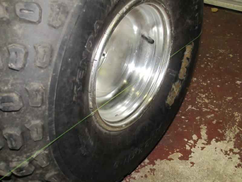
TOE:
The toe of an ATV measures the relation of the leading edge of the front tires to the back of the tires. Toe-out refers to the fact that the front of the tires point out. Toe-in refers to the fact that the front of the tires point in.
Mostly, the recommend setting of your toe-in is ¼ of an inch.
Now you are able to set your Toe on your stock Blaster!
Now that we have established what is what, we need to learn how to set all of this up accurately and symmetrically.
Before you start, you need to check a few things and make your sure you have all the tools you will need. To start with find yourself a garage or level paved surface, then find a spirit level (bubble level) about 1m long and check the levelness of your chosen surface, you may notice a slight gradient in the case of a garage, this is to allow for water to run out the door and not into the corners, bear this slight angle in mind, although it shouldn’t play a huge role.
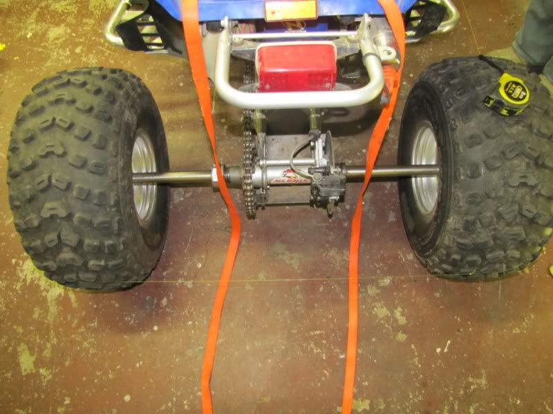
Next, make sure all your tire pressures are equal, set your tires just a little above what you normally ride with them at. It is important to remember that while you may need a stand or a jack to get the wheels off and make adjustments, it is vital to replace them and let the bike stand on its wheels when checking the measurements
Other tools you will need include all your necessary spanners, a shorter 500mm spirit level and ideally an angle finder (contractors protractor) or a clinometer, I was lucky enough to have a Brunton geological compass on hand which incidently is able to measure angles by using a small bubble level and a clinometer built in to it. You will also need a steel ruler, a tape measure and a few other goodies like a notebook, pen and a permanent marker.
Your first port of call when setting up is your caster, followed by the camber and lastly, the toe.
SETTING CASTER:
My A-arms utilize heim joints on the upper A-arms which allow for the adjustment of the top A-arm and setting of the caster, some others do not use this system and instead employ a shim system, regardless of which, the measuring of the caster is exactly the same for both, since I have heim joints, I will be explaining this method.
When you get your top A-arms the first step is to screw in the heim joints all the way, once you have them all in, line them up by ignoring half a turn or so in order to get both joints located on the same axis so a bolt can pass through them. Get a permanent marker and make a mark on the top side of the arm and on the heim joint so you know which way is up and so you can count the turns.
here you can see my upper heim joints:
In order to get your top ball joint behind the back one, you sort of need to twist the arm by turning out only one of the joints, to push the ball joint back, you need to turn the back heim joint OUT, start with 3 complete (360*) turns and leave the front heim at 0 turns, It is handy to have a notebook on hand and keep track of these turns!
Adjusting the heim joints requires you to remove the arm each time and turn the joints, this is a mission but its part of the deal…
Ok so once you have set them as mentioned, assemble the arm, put the wheels back on and let the bike stand on the ground, you may at this point want to simulate rider sag by measuring how much suspension travel you have when you are on the bike and use ratchet tie downs to compress the suspension to the measurement, I for one didn’t find this too necessary because the caster does not change through suspension travel, what is important however is frame angle, if the back is lower than the front, it pushes the bottom ball joint further forward and pulls the top ball joint backwards thus giving more caster than when level, and vice versa for the front end, however in reality, with riding, generally, both front and back will compress at a similar time such as hitting a ditch etc, and although this is very simplified, including suspension travel dynamics will make things VERY complex, for example, do the left and right front suspensions move exactly the same in real life conditions? Not likely and so to keep it simple, I ignored suspension travel, it is important to have the tires on in order to get the basic frame angle right, if you put the front on a stand and lift it up, you are simulating back end compression and thus measuring and setting it up like this will give you false readings.
Ok, so you have 3 turns on the back upper heim joint and 0 on the front, now turn the wheel you are working on the extreme outer limit of its turn and grab your 1m level, position it against the bottom ball joint thread and against the top ball joint thread. If the top of the straight edge leans towards the rear of your quad, you have positive caster. This is what you want. Rest the angle finder on the edge of the straight edge. This will tell you the exact caster setting. You may need to adjust the Heim Joints by turning one in or out more than the other to get the appropriate setting. In my case I used my compass as so…
Do this for each wheel and make sure they are both the same, I had an issue with the front leg of the upper A-arm hitting my spring and so can only achieve 3.5 degrees of caster before I hit the spring.
Once you have a degree measured and set, you can double check this using god old trigonometry! To do this, measure the distance between the thread of the ball joints, mine turned out to be 190mm, then place your level against the bottom thread and lean it away from the top thread until the level is perfectly level, then measure with a ruler the distance between the edge of the upper ball joint thread and the edge of the level. Mine turned out at 12mm.
Once you have these two measurements, you can do a simple trig calculation to work out the angle, I am looking for angle theta and so use sine-1 = Opposite/hypotenuse to work out the angle of caster, in my case my calculations matched my measurements. sine-1 = 12/190 = 3.6 degrees
SETTING CAMBER:
It is important to note that you shouldn’t set your camber until you have set your caster, this is because with the heim joints, screwing the joints in or out directly affects your camber as well as your caster and so it is best to set your caster and then fix up the camber afterwards using the threaded ball joints.
Setting the camber is a much easier process. Rest the straight edge of the level against the outside of your front tire (making sure both wheels are pointing straight and you are touching the same part of the tire, top and bottom). The top of the level should lean inward for negative camber. Now put the angle finder against the straight edge and note the reading. If you need more or less camber than you want or need, you are going to have to remove one of the ball joints in order to adjust it. First remove the split pin and castle nut off of the ball joint, then “smack” the side of the spindle right where the ball joint goes through the spindle to jar the ball joint loose. It will take some pressure to remove it, and it helps if you lift up on the arm itself as your hitting the spindle. For more negative camber, turn the upper ball joint into the a-arm (clockwise). Reassemble and recheck, I got mine in at 3 degrees which looks purposeful
Last edited: