Cad drawing Metal work help

Markblaster

Custom blaster
Dec 6, 2015
2,311
760
175
Hi there all. Any one into CAD drawing and metal fabrication?

Just drawing the lower A arm for my blaster so I can design up a custom aluminum skid plate for them and having problems trying to work out a way to draw the bends in the A arm.

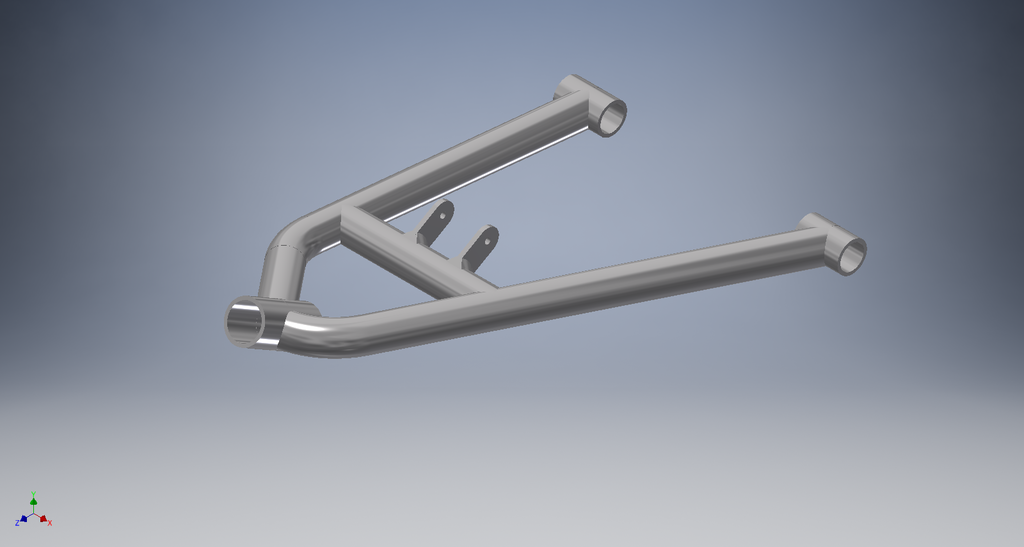
At the moment this is what I have. It is 1:1 scale.
A Arm Skid Plate.jpg

Lower A arms +3 Long travel.
DSCN3894.jpg


Any way to work out what bender diameter die was used or angle it was bent to.

Thanks for any help.
 
Last edited:
I use Coral Draw cuz I'm old but you can use any good draw program. Take measurements from marked locations and take a picture of the part you want to measure .. farther away is better .. less fish eye distortion .. import to draw program and scale till it matches your measurements .. now you can make circles to match radius and rotate lines to read angles .. I've even used this method to find door lines, gas cap covers, mirrors and fender arcs for whole vehicle graphics .. kinda micky mouse but it's worked for me in a pinch for years .. you can also export DXF. I may not have explained this well but it's really pretty quick & easy.
 
I use AutoCAD and Inventor at work. Not so much with AutoCAD as I do with Inventor. Inventor has a really nice sheet metal function where I just do the first face and then I can add bends. If you want, you can PM me what you specifically are wanting to do and I can probably take an hour after work and get a nice 3D model of it and send it back to you to verify. The nice things about the sheet metal function is that you can simply just add bends and you can also unbend the part so that a shop can see what shape to cut out and where to bend it.
 
  • Like
Reactions: Markblaster
It also has a frame generator so that would make modeling the arms a little easier. But to do that I would need a lot of dimensions from you. It would be slightly difficult just because I don't have them sitting in front of me to measure all the angles and sizes of tubing.
 
  • Like
Reactions: Markblaster
I use Coral Draw cuz I'm old but you can use any good draw program. Take measurements from marked locations and take a picture of the part you want to measure .. farther away is better .. less fish eye distortion .. import to draw program and scale till it matches your measurements .. now you can make circles to match radius and rotate lines to read angles .. I've even used this method to find door lines, gas cap covers, mirrors and fender arcs for whole vehicle graphics .. kinda micky mouse but it's worked for me in a pinch for years .. you can also export DXF. I may not have explained this well but it's really pretty quick & easy.

Thanks. Yeah that be another option. Lol Corel draw. My boss loves that program i cannot stand it. Adobe Illustrator for me.

It also has a frame generator so that would make modeling the arms a little easier. But to do that I would need a lot of dimensions from you. It would be slightly difficult just because I don't have them sitting in front of me to measure all the angles and sizes of tubing.

I can take a top down photo of my lower a arm and email you my file of what I have drawn so far. Also can supply all measurements. Flick me a PM with your email addy. Will email you a DXF and PDF.
 
hello! do you have the CAD drawing for the skid plate to cover under the chasis? thanks in advance!