Could you not just make that top plate out of 2 parts? Not bend it. Have the back part on the red line like Herpderplol has drawn and have the other part closest to the pivot point flat as it is.
New Custom YFZ450 Linkage Swingarm Design
- Thread starter Blaner
- Start date
You are using an out of date browser. It may not display this or other websites correctly.
You should upgrade or use an alternative browser.
You should upgrade or use an alternative browser.
That could be done, but thats an extra weld right in the middle. It would look terrible if the weld wasnt flat or ground downCould you not just make that top plate out of 2 parts? Not bend it. Have the back part on the red line like Herpderplol has drawn and have the other part closest to the pivot point flat as it is.
Nope not yet. At the moment, the front baring tubes are being machined to accommodate a custom needle roller. Looking to use a self contained needle roller and race, like a sealed bearing. This will eliminate the pitting on the inner tubes that always occurs on these things. Problem with that is that the outer diameter of the housing needs to be 38.5mm and not 35mm. So a little machining is going on. I have a friend helping me out with that at the moment. Il have more intel for you later this week.
As for the carrier Awk, I know the design will accommodate the carrier because I used the exact same CAD design on my last swingarm. The only factor is the ride height that can be set by adjusting the angle of the "wings" in relation to the front mount. I had this adjustment on my last design, but the nature of the one piece plate eliminates this option. The ride height will then be set by the location of the Linkage mount position on the swingarm. That I will do when I mock it up and see where thigs lie with the bike hoisted tot the correct height.
Well I have been out of town for a while, but my front end tubes are ready, I must go collect. Then it needs to be welded etc. Il get pics asap!!
Hi guys,things have taken a while to get moving again here, but have fetched my parts from a friend who machined them for me. I had the bearing carrier inner and outer tubes made as well as a spacer tube to keep things 100% aligned and spaced when welding.
Have a look:
Here we have all the news bits:

The outer bearing holder. This will be welded onto the rest of the swingarm.

The outer tubes with the spacer. You can see the two grooves , these will be used to cut through to remove the center piece between the grooves. That will then allow for the spacer to be removed once its welded up.

Here we have the spacer in "exploded"view. You can see the recessed lip that fits inside the two loose tubes to make sure everything is 100% lined up

These are hardened sleeves fitted onto the inner tubes. The needle rollers will run on these hardened surfaces and not the main inner tube as per factory setup. This will allow for just the sleeves to be replaced when required and not the whole tube!

Complete breakdown showing oil seals a, bearings, etc.

Hi Guys, im slow, I know, this one has me head scratching to no end! Better slow and sure than find a bind and grind!
The arm has been tacked together, I have also positioned the front bearing tubes in line to make sure the sprocket is inline with the chain. I used the spacer to accurately space the tubes apart to allow clearance for the motor and it worked 100%.
Test fitting looks promising. The big "X" is the linkage location and geometry. Its hard to know where to mount the Dog Leg onto the frame and where to mount the other end of the linkage to the swingarm so that the linkage rotates in all the right arcs and does not bind while the swingarm goes through its travel.
The other issues to getting the shock to operate throughout its compressive capacity and the key to match shock travel to swingarm travel. You dont want to run out of shock and linkage travel when you still have physical space for the winger to move on compressions but run out of swingarm travel and still have shock and linkage travel to space on rebound/extension.
How do we do this? Well i have some measurements from a 450, im sure they will help as a guide but the blaster frame is very different to the 450. The upper shock mount, swinger pivot point and base of frame and all in a vertical line, one above the other. The 450 has these components in an offset manner to accommodate the linkage. So I need to work this out carefully.
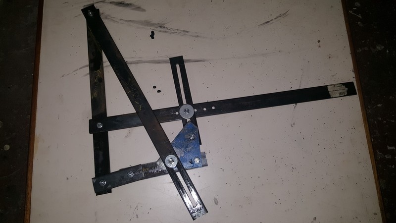
I have decided that making a 1:1 scale 2d model out of 30mm flat bar with drilled and slotted holes to be bolted together will be the way to test these positions. This will allow me to move the potential linkage positions to a variety of lengths and along arcs to find the points where the system works best.
I have done all the required measurements and now just need to build it!
Here we go so far:

Had to adjust the front edge of the plates to fit the bearing tubes in snuggly!

Tacking...

Test fitting

YFZ450 Shock fitting on 400ex bushes!


Shock passing through swingarm with linkage at the bottom.

Doing some measurements

YFZ450 suspension configuration

Swingarm Model plans

Swingarm model plans drawn to scale on Autocad
The arm has been tacked together, I have also positioned the front bearing tubes in line to make sure the sprocket is inline with the chain. I used the spacer to accurately space the tubes apart to allow clearance for the motor and it worked 100%.
Test fitting looks promising. The big "X" is the linkage location and geometry. Its hard to know where to mount the Dog Leg onto the frame and where to mount the other end of the linkage to the swingarm so that the linkage rotates in all the right arcs and does not bind while the swingarm goes through its travel.
The other issues to getting the shock to operate throughout its compressive capacity and the key to match shock travel to swingarm travel. You dont want to run out of shock and linkage travel when you still have physical space for the winger to move on compressions but run out of swingarm travel and still have shock and linkage travel to space on rebound/extension.
How do we do this? Well i have some measurements from a 450, im sure they will help as a guide but the blaster frame is very different to the 450. The upper shock mount, swinger pivot point and base of frame and all in a vertical line, one above the other. The 450 has these components in an offset manner to accommodate the linkage. So I need to work this out carefully.
I have decided that making a 1:1 scale 2d model out of 30mm flat bar with drilled and slotted holes to be bolted together will be the way to test these positions. This will allow me to move the potential linkage positions to a variety of lengths and along arcs to find the points where the system works best.
I have done all the required measurements and now just need to build it!
Here we go so far:

Had to adjust the front edge of the plates to fit the bearing tubes in snuggly!

Tacking...

Test fitting

YFZ450 Shock fitting on 400ex bushes!


Shock passing through swingarm with linkage at the bottom.

Doing some measurements

YFZ450 suspension configuration

Swingarm Model plans

Swingarm model plans drawn to scale on Autocad
Last edited:
Looking good !!
Just a suggestion , but if you have ability to , remove shock spring for testing for binding.
Just a suggestion , but if you have ability to , remove shock spring for testing for binding.
I have since removed the spring, I was also looking at the physical fitting of the spring through the swingarm. I wasnt sure if the spring would jam on the swinger as it moves(ie. is my cutout big enough??!!) Im still not sure, but It looks like it may be ok!Looking good !!
Just a suggestion , but if you have ability to , remove shock spring for testing for binding.
Short piece of pipe, tubing, rolled up poster board to simulate outside diameter of spring, taped in place.
You are at the point of making sure all the little details are spot on.
You are at the point of making sure all the little details are spot on.
Good Idea. Want to have a look at the model this eve and tomorrow morning. Hopefully can make some progress. Another lurking concern is the fact that the linkage hangs below the swingarm. While this is common practice on other bikes, I hope it doesn't end up being a hindrance to me hitting into all and sundry. I will have to make a more comprehensive skid plate...
Right, finally some proper progress guys.
It’s been an interesting last few weeks, with much thought being given to how this linkage business is going to work out. After getting my head around some leverage ratio physics, cutting, grinding, welding and measuring, I finally have something that is going to work.
Once we had the swingarm plugged together A-la-Lego style, we tacked it together and positioned the front bearing tubes with the swinger on the bike and zapped it all in place. That was the easy part.
Now for the linkage system…well goodness me I though the front end YFZ swap was complicated, this one had me stumped for a while. However at the end of the day, it is actually pretty simple. The bamboozling bit is that there are so many moving parts. I tried to build a 3D model to simulate the linkage, and although it helped get to grips with what was going on and what each component did and how it influenced the system, it never accurately showed me how it would work in real life.
My model looked something like this:

The trick turned out to be the relationship between ride height, the maximum and minimum travel measurements as well as the shock travel and linkage travel. All of these components need to work in harmony to have a rideable bike. You don’t want the shock to bottom out while your ride height is still far from compressed and vice versa.
Essentially what I did was get the seat height of my brothers YFZ450 and use that as a guide, being that that bike is well setup and suits me well, I thought using this would be a good benchmark. I then winched the frame, leaving the wheels behind to set the bike at the same seat height. We then fiddled with the shock and linkage to work out where it should sit. Once we found rough positions, it seemed as though the system would hang far too low below the bike, increasing the risk of damage from passing over rocks etc. To fix this we relocated the top shock mount by 30mm. We also relocated the bottom hole in the shock by 20mm. This made things a lot better and tucked the linkage away nicely under the swingarm.


The next step was to figure out what my linkage ratio is and what it should be. But wait, what is that? I hear you ask…The linkage ratio is the ratio of force applied along a lever. If you apply 1F to the axle, and your shock is located half way along the swingarm, your shock is exposed to 2F. This can be viewed as a ratio of 2:1. The bigger the ratio, the softer the system, a 1:1 ratio is very hard! Now on a bike such as the blaster with a fixed bottom shock position, this ratio is a constant. The advantage of a linkage is that it makes the suspension “progressive” This means that it actually changes the leverage ratio as it moves through the bikes travel. This means that the suspension is soft on the small bumps and firm on the big bumps!
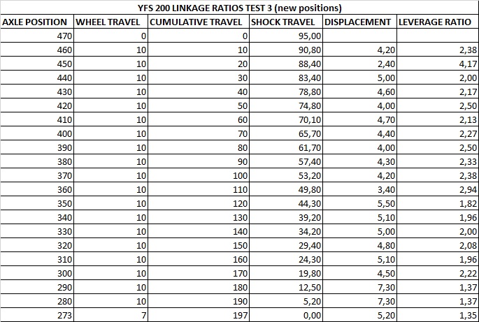
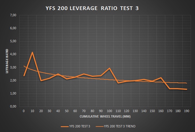
Having the linkage positions clamped down, we could test a variety of different arrangements to give us what we need. We started by getting the ratio off of the 450. This is pretty simple! Set the bike at max extension without the spring. I suspended the chassis from a block & Tackle and then placed a jack under the axle carrier. I found a position on the axle and the frame and jacked the wheels up at 10mm increments. At each increment, I measure the shock travel. You then divide the wheel travel by the shock travel and that gives you a linkage ratio!

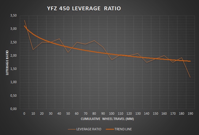
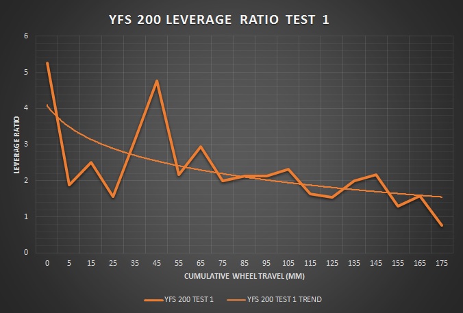
I used some angles obtained via an inclinometer app on my phone to position the blaster linkage as closely as possible to the 450’s and then tested my linkage ratio. As you can see, my first two attempt gave a much more aggressive ratio, meaning the bike would be softer at first and then harder at the end of the travel. At least it was doing the right thing and the graph was showing it was a progressive system and not regressive!


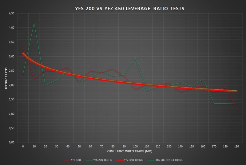
After we did the shock shortening and a few other things I retested and found something remarkable. My linkage ratio came out near exactly the same as the 450!

Happy with that, we moved on the attachment and welding…
We came across a snag when welding up the front bearing tubes…once welded up, they turned oval ever so slightly. Just enough to prevent to bearing from being pressed in easily and when they were pressed in, they were deformed and wouldn’t allow the inner tubes to be inserted…We managed to solve this problem (temporarily) by sanding the holes, I still need to take it in to get machined to fix this properly!
After that, it was welding and welding. The tricky part being attaching the dog bone mounting to the frame. The blaster frame isn’t too thick and mine isn’t in the best condition along that back frame bar.
Finally I was relieved to find that my shock cut-out on the swingarm was just big enough and that the spring passed though and operated well within the cut-out I had made.


Now I have the bike standing and it feels good. Wheel travel is 2mm more than the YFZ450. Not bad I think!
I have to still resolve my bearing issue and finish off a few welds.
It’s been an interesting last few weeks, with much thought being given to how this linkage business is going to work out. After getting my head around some leverage ratio physics, cutting, grinding, welding and measuring, I finally have something that is going to work.
Once we had the swingarm plugged together A-la-Lego style, we tacked it together and positioned the front bearing tubes with the swinger on the bike and zapped it all in place. That was the easy part.
Now for the linkage system…well goodness me I though the front end YFZ swap was complicated, this one had me stumped for a while. However at the end of the day, it is actually pretty simple. The bamboozling bit is that there are so many moving parts. I tried to build a 3D model to simulate the linkage, and although it helped get to grips with what was going on and what each component did and how it influenced the system, it never accurately showed me how it would work in real life.
My model looked something like this:


The trick turned out to be the relationship between ride height, the maximum and minimum travel measurements as well as the shock travel and linkage travel. All of these components need to work in harmony to have a rideable bike. You don’t want the shock to bottom out while your ride height is still far from compressed and vice versa.
Essentially what I did was get the seat height of my brothers YFZ450 and use that as a guide, being that that bike is well setup and suits me well, I thought using this would be a good benchmark. I then winched the frame, leaving the wheels behind to set the bike at the same seat height. We then fiddled with the shock and linkage to work out where it should sit. Once we found rough positions, it seemed as though the system would hang far too low below the bike, increasing the risk of damage from passing over rocks etc. To fix this we relocated the top shock mount by 30mm. We also relocated the bottom hole in the shock by 20mm. This made things a lot better and tucked the linkage away nicely under the swingarm.


The next step was to figure out what my linkage ratio is and what it should be. But wait, what is that? I hear you ask…The linkage ratio is the ratio of force applied along a lever. If you apply 1F to the axle, and your shock is located half way along the swingarm, your shock is exposed to 2F. This can be viewed as a ratio of 2:1. The bigger the ratio, the softer the system, a 1:1 ratio is very hard! Now on a bike such as the blaster with a fixed bottom shock position, this ratio is a constant. The advantage of a linkage is that it makes the suspension “progressive” This means that it actually changes the leverage ratio as it moves through the bikes travel. This means that the suspension is soft on the small bumps and firm on the big bumps!
Having the linkage positions clamped down, we could test a variety of different arrangements to give us what we need. We started by getting the ratio off of the 450. This is pretty simple! Set the bike at max extension without the spring. I suspended the chassis from a block & Tackle and then placed a jack under the axle carrier. I found a position on the axle and the frame and jacked the wheels up at 10mm increments. At each increment, I measure the shock travel. You then divide the wheel travel by the shock travel and that gives you a linkage ratio!


I used some angles obtained via an inclinometer app on my phone to position the blaster linkage as closely as possible to the 450’s and then tested my linkage ratio. As you can see, my first two attempt gave a much more aggressive ratio, meaning the bike would be softer at first and then harder at the end of the travel. At least it was doing the right thing and the graph was showing it was a progressive system and not regressive!


After we did the shock shortening and a few other things I retested and found something remarkable. My linkage ratio came out near exactly the same as the 450!


Happy with that, we moved on the attachment and welding…
We came across a snag when welding up the front bearing tubes…once welded up, they turned oval ever so slightly. Just enough to prevent to bearing from being pressed in easily and when they were pressed in, they were deformed and wouldn’t allow the inner tubes to be inserted…We managed to solve this problem (temporarily) by sanding the holes, I still need to take it in to get machined to fix this properly!
After that, it was welding and welding. The tricky part being attaching the dog bone mounting to the frame. The blaster frame isn’t too thick and mine isn’t in the best condition along that back frame bar.
Finally I was relieved to find that my shock cut-out on the swingarm was just big enough and that the spring passed though and operated well within the cut-out I had made.


Now I have the bike standing and it feels good. Wheel travel is 2mm more than the YFZ450. Not bad I think!
I have to still resolve my bearing issue and finish off a few welds.
Last edited:
Most recent update is that I ran into some trouble with fitting the needle rollers...turns out the welding of the front tubes caused them to distort into a slight oval, making the bearing press in with some difficulty. the down of it all was that the inner roller tubes wouldn't fit  . This could not be fixed with a line bore as I had a step inside to stp the bearing at the right place and also for strength. I opted to use a drum sanding roll and a brake cylinder honing tool to get the tubes back to spec! In the mean time I have been designing a new skid plate to cover the linkage and a general cleanup all round. Should have it going by the weekend!
. This could not be fixed with a line bore as I had a step inside to stp the bearing at the right place and also for strength. I opted to use a drum sanding roll and a brake cylinder honing tool to get the tubes back to spec! In the mean time I have been designing a new skid plate to cover the linkage and a general cleanup all round. Should have it going by the weekend!Similar threads
- Replies
- 0
- Views
- 55
- Replies
- 11
- Views
- 612
- Replies
- 14
- Views
- 260