Hey guys, i recently decided a front suspension upgrade was necessary on my blaster and came across a complete YFZ450 front suspension on a local buy/sell website. The guy was selling the a arms and shocks. Tubes and bushes included but no grease caps. This wasn’t an issue as I just used the blaster grease caps which fit right onto the 450 a arms. I must add that these were off a 2005 YFZ, and my measurements to follow all came off a 2004 YFZ. If you use a new 450R, things will be very different as that bike has a whole new chassis etc.
The whole project which included a motor rebuild and a swingarm extension and Honda 400ex shock insertion took about 4 weeks. Since there is plenty of info around the site about motor rebuilds and rear suspension mods im not going to touch on that side but as there is much debate and difficulty around modding the front suspension and since i don’t think there is a complete post like this on this site I decided to do a fairly complete guide to fitting a YFZ450 front suspension to a blaster! I will be giving all my measurements in millimetres and metric units so you may need to do some converting if you decide to use this as a guideline when doing your own conversion! PLEASE NOTE that this is ONLY a guideline, a “get the picture” sort of thing and your own initiative, common sense and fathoming out will be necessary to do this properly
Now lets get under way with some basic things you need to know before undertaking this job. Firstly let it be known that this is a pretty tough job and you going to need some serious brain power and good arithmetic skills in the garage to make the necessary quick calculations when measuring up your new mounts, however, don’t be afraid! If you are fairly well equipped in your tool department and have some pretty good mechanical experience you will be fine, I wouldn’t really recommend you try this if you are not confident and are not too great with fabrication, if you managed your own custom extended swingarm you should get this right. You will also need some knowledge and skill on how to wield a welder , handle a hacksaw and grip a grinder You also going to need a drill press of sorts, but i suppose you could get away with using a hand drill, you will just need to be very accurate with that! This is a DIY job but its more like a DIYWSH (do it yourself with some help) so if you have a buddy who is well skilled in fabrication and the like, get him in on your project and have him help you.
Tools you will need: a GOOD hacksaw, some 18 and 24 tooth hacksaw blades, a welder, various drill bits up to 10mm, a drill press, an angle grinder, steel grinding and cutting disks, flap type sanding disks for the angle grinder 80 or 120 grit, a couple of “G”clamps, some vice grips (hand held type), a bench vice, a work bench, a bench grinder, tape measure, vernier calliper (digital will be best), 300mm steel rule, 150mm steel rule, a small hammer, 2x lengths of 10mm threaded rod (cut to 350mm), some bolts for the threaded rod (x8) A steel Scribe, a small steel engineers setsquare, a pencil, a permanent marker.
I can’t stress enough that accuracy and precision is VERY important in this job as drilling or welding your new custom mounts just a few mm’s out of line is going to be costly on your finished product. Your suspension needs to be symmetrical on left and right for the geometry to work. Settling for second best when you realise a measurement is wrong after youve tact a weld is just not going to work. Patience will get you far in this project. In many cases, having a bolt hole out of line just wont work and you will have to take it loose the weld in any case.
As I used the 450 suspension, I thought it apt that the geometry of my conversion should match a 450, i.e. the distance between the lower and upper a arm mounts and the distance between left and right mounts, front and back, shock angle etc, thus matching things such as caster and camber. Fortunately, i have access to an yfz450 so i measured up the 450 and applied the measurements to the blaster setup to make sure everything works as it does on the 450. I will include these measurements as i go so you can get a good idea if you decide to do this about what to measure and a ball-park figure as I assume every bike will be somewhat different.
In case you don’t know, the YFZ450 suspension WILL NOT FIT or bolt directly onto a stock blaster. It just doesn’t happen for a number of reasons.
1. Blasters have different sized a arms ball joints, 450s are both the same. (upper and lower)
2. The bottom a arms are wider from grease cap to grease cap (front to back) than blasters hence they don’t fit into those mounting boxes on the frame
3. The 450 top a arms are also wider grease cap to grease cap and don’t fit between the blaster mounts on the frame.
4. The 450 shock is much longer than the blaster shocks and therefore the top mounts on the blaster frame are in the wrong place.
So basically, you need to make new mounts for everything! Sounds intimidating – and it is - but there is a way!
Once you have the YFZ a arms and shocks, you are also going to need to find yourself a pair of spindles. Now you CANT use the stock blaster spindles as the one ball joint socket is a different size whereas both the upper and lower ball joints on the 450 are the same size. Ideally, it would be best to use spindles from a YFZ450, but in my case i found they tend to be a bit more expensive than spindles from any of the other Yamaha quads so at first I located a pair from a banshee. However i soon realised these will not work as although the ball joint sockets are a match for the 450 a arm ball joints, the angle at which the sockets are located results in the ball joints being under too much tension and are pushed skew. I scrapped that idea and found a nice set of Raptor 660 spindles! Aha! These work perfectly, so, in my books, find yourself either 450 or 660 spindles for the job.
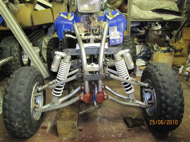
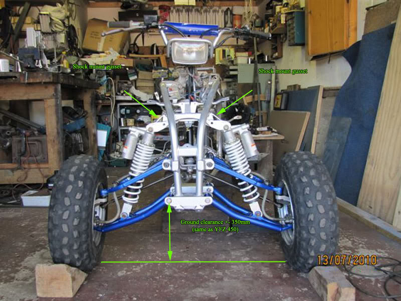
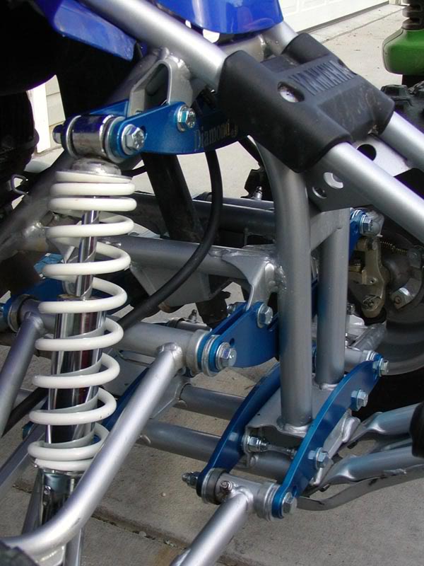
Although this Pic has the rear shock in, I didn’t get that from the guy, I used a 400ex shock for that.
While I was at it I got a set of Banshee callipers and a master cylinder as i decided to switch from the old drums to hydro’s. If your blaster is post 2003, you can use your same callipers and this will save you a bit of time and money!
One other thing you will need is a pair of YFZ450 tie rods. This is because once the 450 stuff is mounted, your blaster will be quite a bit wider than stock and the blaster tie rods are about 85mm too short! You can use your blaster tie rod ball joints here so you only need to get the actual tie rod. Once you have them, unscrew the ball joints from the blaster tie rods and put them into the 450 tie rods. Note that these things have a reverse thread on one side so remember that when you can’t unscrew them and end up stripping the nut!
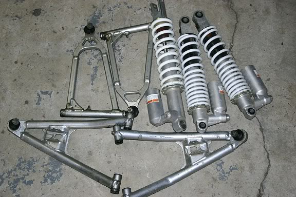
Right, now that you have all the bits, you need to strip your blaster and throw that stuff as far away as possible, before you do though, just lay out the a arms and shocks and compare them to the 450 kit, this will serve as an inspiring moment as you are blown away by the shear “betterness” of your new kit compared to the crusty bits that came off your blaster, you will now understand why you used to rattle your arms off going as fast as possible trying to keep up with your buddy on his 450. Doing this will help you visualise the changes that need to be made and will give you a better understanding of what needs to be done.
At some point you need to get stuck into your frame with a grinder and a cutting disk to remove all your old a arm mounts. But just check the new arms against the old mounts to get the idea as well before you cut them off.
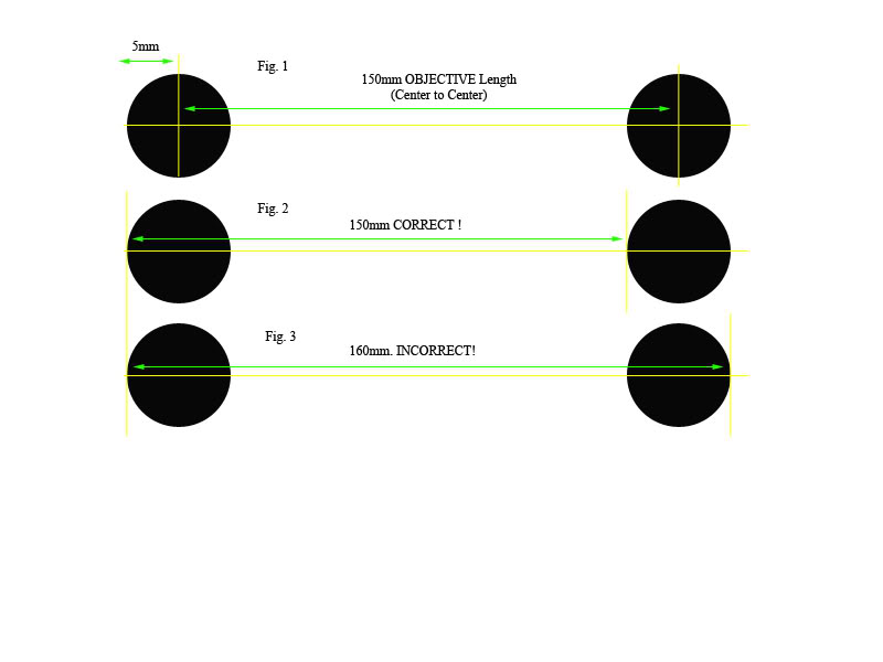
Here is a list of the measurements of the stock blaster suspension geometry: (all measurements taken centre to centre of bolt holes)
Here is how to measure centre to centre distances:
BLASTER:
• Top A Arm: 175mm apart horizontally
• Bottom A Arm: 145mm apart horizontally
• Setback between top and bottom arms: 35mm
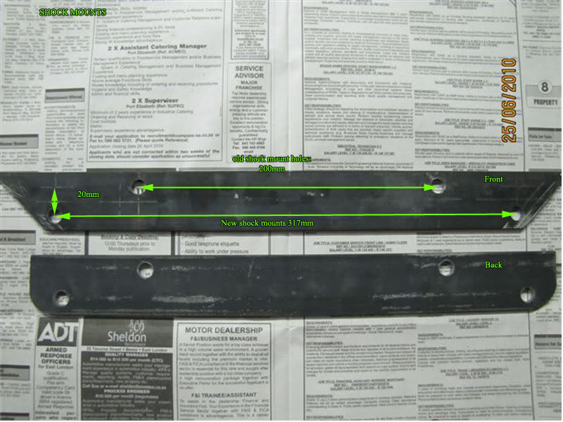
• Top shock mounts 200mm apart horizontally
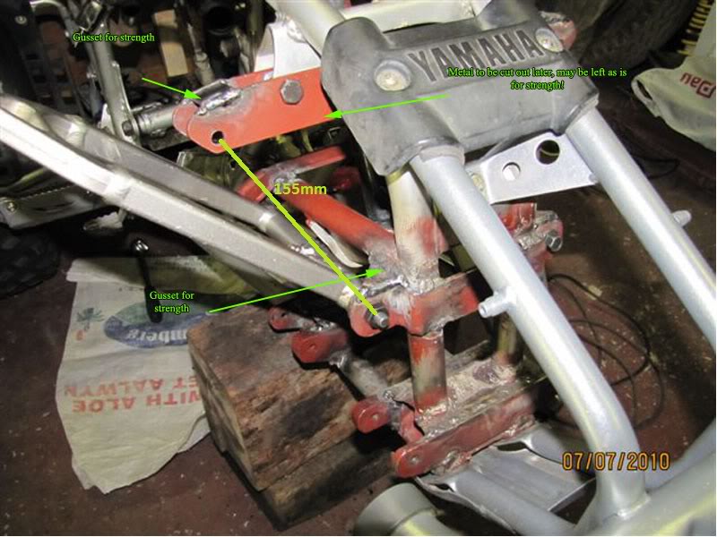
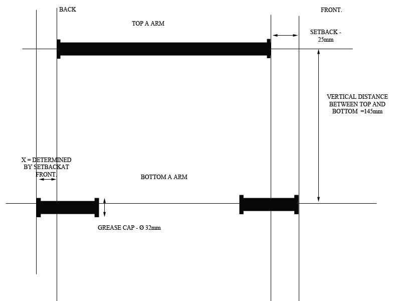
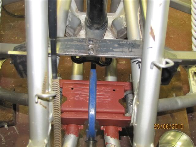
(The setback is the distance the top a arm bracket sits behind the bottom a arms bracket This is critical to your caster. – SEE PIC BELOW)
• Vertical Distance between top and bottom mounts: Didnt take note, irrelevant.
YFZ 450:
• Top A Arm: 160mm apart horizontally
• Bottom A Arm: 140mm apart horizontally
• Setback between top and bottom arms: 25mm
• Top shock mounts 300mm apart horizontally
•
(the setback is the distance the top a arm bracket sits behind the bottom a arms bracket .This is critical to your caster.)
• Vertical Distance between top and bottom mounts: 145mm
**All Bolts are 10mm 1.25mm pitch thread. Both blaster and 450.
Order of the Procedure:
The whole project depends on where you start. Your final position of your top a arm rear mount is dependent on your mounting position at the front. Which is dependent on TWO things, your setback from the bottom a arm mounts, and your height from your bottom a arm mounts, thus it makes sense that the bottom is the place to start! Just as a note, pay careful to the setback as mentioned earlier as this is fundamental to the caster. If the top a arm is ahead of the bottom, the top ball joint will also be ahead and thus wont allow the wheel to self centralize like a shopping trolley and will make the bike a real pain to drive!
Ok, so we start at the bottom, but here too, the rear mounts of the bottom a arms are completely dependent of the fronts position as the arm is a fixed width. So if you work from the back, chances are you will end up having the front mount hanging out in front of the bike and will be awkward to work with, so to avoid this, we start the whole project with the front mount of the bottom a arm.
Your next step is where things start to get interesting. The first point at which to start is with the bottom a arm mounts. If you hold the 450 arm against the blaster mounting point you will notice the new arm is much wider (front to back). You need to make new mounts for the 450 arm.
The bottom Mounts:
I used 8x30mm flat bar for this part. The horizontal distance between the stock mount holes is 145mm. REMEMBER to measure from centre to centre of the holes. This is done by measuring from the outside edge of the first hole to the inside edge of the second hole. I.e. PICTURE! Do this with the vernier calliper. Know how to do this, as this principle is fundamental in your project, if you get it wrong and measure from outside to outside everything will be very wrong! Pay attention when measuring, it is CRUCIAL! Now the distance between the mount holes on a 450 is 140mm. This is closer together than the stock blaster which is 145mm so now what? Well this is where the compromise comes in. The only solution to this is to make your new mount holes a bit wider than the stock 450.
But before you get carried away, there is another VERY important aspect we need to make clear in terms of keeping the geometry of the 450. If you notice the measurements mentioned earlier,
I.e.:
BLASTER:
• Top A Arm: 175mm apart horizontally
• Bottom A Arm: 145mm apart horizontally
• Setback between top and bottom arms: 35mm
• Vertical Distance between top and bottom mounts: Didn’t take note, irrelevant.
YFZ 450:
• Top A Arm: 160mm apart horizontally
• Bottom A Arm: 140mm apart horizontally
• Setback between top and bottom arms: 25mm
• Vertical Distance between top and bottom mounts: 145mm
You will notice that the DIFFERENCE between the 450’s top arm distance and the bottom arm distance is 20mm, while the blasters is 30mm.
Therefore in order to keep the 450 geometry, we need to keep this ratio between the top and bottom mounts the same, i.e. 20mm.
With this in mind, we look at the maximum or closest distance we can mount the arms to the blaster frame by looking at the widest point, which in this case is 175mm at the top a arm of the stock blaster. Therefore, we have a catch! If you make the bottom mounts and drill holes at say, 145mm apart and weld them on, your top mounts are not going to work as you won’t be able to keep the ration of 20mm between top and bottom! (145mm + 20mm = 165mm and our closest distance we can go is 175mm) that would mess up the whole thing and the bike would turn out a mess with very bad camber.
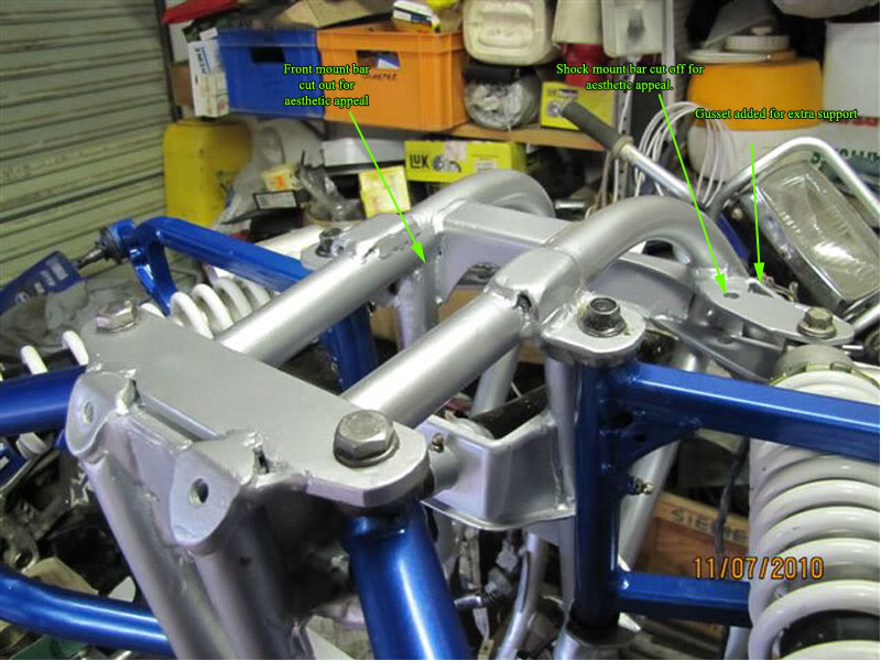
So a solution – the compromise as promised. Ideally, you want your arms mounted as close together as possible, it allows for maximum suspension travel and agility, look at the new 450R, the a arms are right together. Think about a Big bird with wide body and tiny short wings, its not going to fly very well...but think of a thin, elongated bird with long wings, much more agile and suitable! – same principle with a quad, that is why these things below are a waste of time... You get the width, but at the cost of handling performance...What you really want is longer arms mounted closer together leaving you with a wide stance but still giving good travel!
 NOT COOL
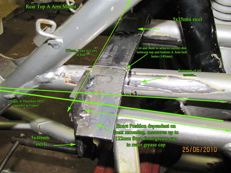
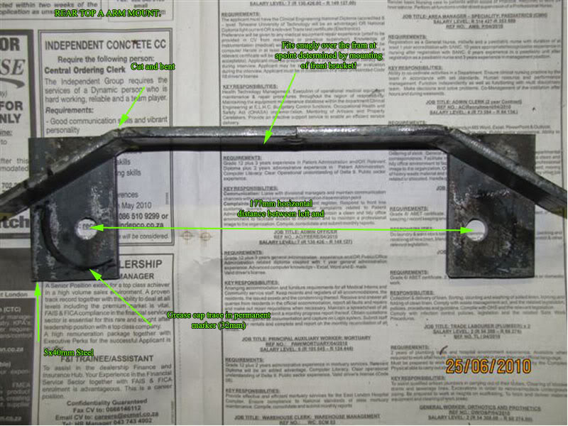
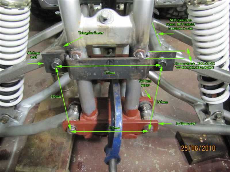
So the solution, eventually! In order to keep the ratio of 20mm the same, we need to look at the minimum top vertical distance and subtract 20mm to give us the minimum distance our bottom arms can be mounted. This leaves us with 175mm + 2mm for clearance purposes = 177mm for the top a arms vertical distance and 177mm – 20mm = 157mm for the bottom vertical distance! As in the pic below. The only thing here is that the bike will end up 17mm wider than a stock 450.
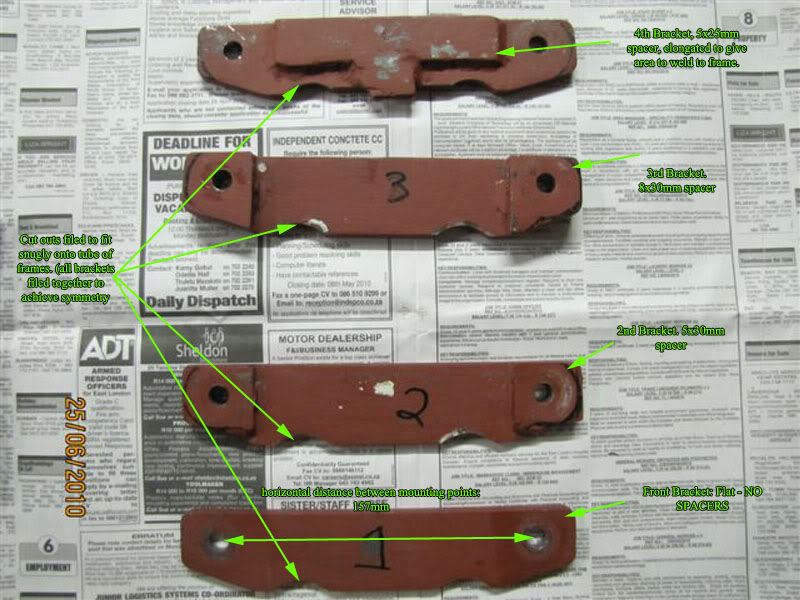
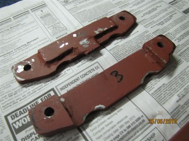
As i mentioned, i used 8x30mm steel bar for the bottom mounts, it is a bit overkill and you could probably get away with using thinner stuff to save a bit of weight!, you will notice i marked them 1 – 4 in the above picture, that is from front to back respectively. The Bolt holes are 157mm apart from centre to centre but when you cut the lengths, remember to make them long enough to hold a grease cap of 32mm diameter. That means from the centre of the bolt, add 5mm for half the bolt hole and then 16mm for half the grease cap. Do this on either end and the bar will be long enough. I.e. 157mm + 5mm + 5mm + 16mm+16mm =199, or 200mm to be round, Once you have cut the bars (x4) find the centres of them all. I suggest clamping them all together and cutting and grinding to the correct length so they are all 100% the same length, mark the centres all together too. Use a G clamp. Once you have the centres, measure 157 /2=78.5mm left and right from the centre line and scribe it nicely using a set square. You will now have the line upon which you will drill the holes, but you still need the Y axis position. This one is a bit more tricky and is probably the most inaccurate part of the whole procedure. You want the new brackets to fit nicely onto the half rounds of the frame that are present on a blaster and if you put the flat bar you have just cut on the tubes they lie above the level of the two boxes on the frame that the old arms fitted into. Put one in front of each box and one behind each box. While they standing above the boxes, measure how high they stand above the boxes. So, we want them to fit over the round tubes and lie flush with the boxes, so, with a vernier calliper, measure the outside distance of the two tubes running parallel to each other. I’m uncertain of the measurement as i didn’t write that one down. Anyway, follow the same procedure as for the previous scribe line by halving the measurement and scribing that distance on either side of the centre line. But, also measure the thickness of the frame, i think it is 27mm, depends on how think your paint is. Half that and measure the half distance in toward the centre line from the line you just scribed, this will mark the centre of the tubes of the frame. Now along those centre of tube lines, mark off the distance that the bars stood above the boxes. You must file up until that line. Get hold of a good round file and start filing! Use a grinder if you want just do it carefully. Remember to clamp all the brackets together while filing to keep them all the same! VERY NB that they are all the same or else they will sit in different positions on the frame...not cool. See the pic above to see the semi circles i filed on the brackets. Ok, very confusing. Bottom line is that the semi circles you must file on the bars must be wide and deep enough to allow the bars to rest over the frame and settle at the same height as the existing a arm mount boxes on your blaster at the same time not letting the semi circles to move you off centre! Watch out for this.
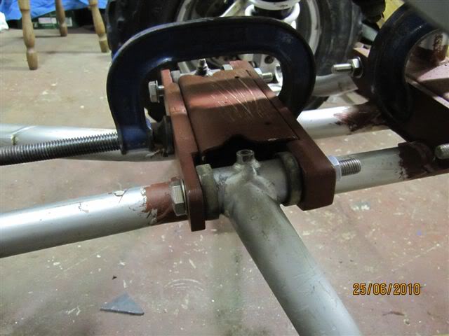
Once you have done that, find the centre of the bars along the vertical scribe line (157mm line) and mark it, it may have changed due to the filing, just make sure you can still fit in a 32mm grease cap without it hitting your frame. The next step is to punch the marks where the two lines intersect and drill them these holes will be your bottom a arm bolt holes. I drilled them all clamped together as it ensured all the bolt holes are in the exact same places! This is obviously very important! Start the drilling with a small bit, 6mm and go up in sequence to 8mm and finally 10mm. This should leave you with 4x flat bars with holes all in the same place and with identical cut outs at the bottom. You can now place them on your frame to see how it looks, Clamp them in place with G clamps as seen in above pic. Once its all clamped up, place the a arm in position. You will notice that the arm doesn’t fit, don’t stress, its ok! We need spacers!
At this point it would be wise to use a length of threaded rod with some nuts, push the rod through each arm while going through all the brackets. Put the nuts on the inside after youve gone through the first block. Position the arm against the front bracket which is pressed tightly to the front of the front box. Measure the gap at the back of the front box to the end of the front leg of the arm (sounds weird hey?) and you will see that you will need a 5mm spacer in there for it to be a tight fit between grease cap and bracket.
With the arm still pushed up against the front, do the same for the back, We want to arm as far forward as possible, so the back will fall into line dependant on the front position. You should measure a gap of 5mm on bracket 3 and notice the arm extends beyond the end of the back box, so a different spacer is required for bracket 4. SEE PIC! This is actually easier than it sounds, once you have it in front of you, it will all make sense.
Next step is to cut all you spacer bits with a hacksaw and then WELD them onto your brackets! Make sure they are square! Once welded, put them under the drill press and drill them out following the hole you just drilled through the main bracket. Clamp up the brackets with spacers in a mock up fashion and test the a arm, it should go in snugly! And there we have your bottom mounts!
Another trick i used was to mark the centres of the two boxes. So when you clamp up the brackets, line the centre lines of each bracket with the centre line of the boxes, then slip in the threaded rod and make sure it can move in and out freely, if it doesn’t, you need to correct the bracket by filing the problematic brackets half rounds to suit. DONT make your bolt holes bigger as a quick fix! If you were accurate enough, it should all line up. Try tapping the bracket which is out of line with a hammer once clamped to try and slide it into line. If that doesn’t work, correct your filing.
Once you are happy with the bottom, bolt it up while clamped, DONT weld it to the frame yet! Now you are ready to start with the top mounts.
Overall, the distance from the inner face of the front mount to the inner face of the back mount should be 258mm.
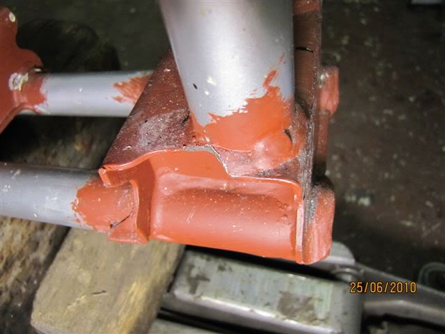
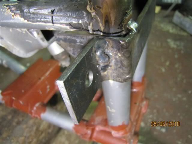
This the stock blaster a arm box at the front bottom. You will notice I had to file the grease nipple cut out quite drastically to get the 450 grease nipples to swing passed when the arm is moved. Do this!
The whole project which included a motor rebuild and a swingarm extension and Honda 400ex shock insertion took about 4 weeks. Since there is plenty of info around the site about motor rebuilds and rear suspension mods im not going to touch on that side but as there is much debate and difficulty around modding the front suspension and since i don’t think there is a complete post like this on this site I decided to do a fairly complete guide to fitting a YFZ450 front suspension to a blaster! I will be giving all my measurements in millimetres and metric units so you may need to do some converting if you decide to use this as a guideline when doing your own conversion! PLEASE NOTE that this is ONLY a guideline, a “get the picture” sort of thing and your own initiative, common sense and fathoming out will be necessary to do this properly
Now lets get under way with some basic things you need to know before undertaking this job. Firstly let it be known that this is a pretty tough job and you going to need some serious brain power and good arithmetic skills in the garage to make the necessary quick calculations when measuring up your new mounts, however, don’t be afraid! If you are fairly well equipped in your tool department and have some pretty good mechanical experience you will be fine, I wouldn’t really recommend you try this if you are not confident and are not too great with fabrication, if you managed your own custom extended swingarm you should get this right. You will also need some knowledge and skill on how to wield a welder , handle a hacksaw and grip a grinder You also going to need a drill press of sorts, but i suppose you could get away with using a hand drill, you will just need to be very accurate with that! This is a DIY job but its more like a DIYWSH (do it yourself with some help) so if you have a buddy who is well skilled in fabrication and the like, get him in on your project and have him help you.
Tools you will need: a GOOD hacksaw, some 18 and 24 tooth hacksaw blades, a welder, various drill bits up to 10mm, a drill press, an angle grinder, steel grinding and cutting disks, flap type sanding disks for the angle grinder 80 or 120 grit, a couple of “G”clamps, some vice grips (hand held type), a bench vice, a work bench, a bench grinder, tape measure, vernier calliper (digital will be best), 300mm steel rule, 150mm steel rule, a small hammer, 2x lengths of 10mm threaded rod (cut to 350mm), some bolts for the threaded rod (x8) A steel Scribe, a small steel engineers setsquare, a pencil, a permanent marker.
I can’t stress enough that accuracy and precision is VERY important in this job as drilling or welding your new custom mounts just a few mm’s out of line is going to be costly on your finished product. Your suspension needs to be symmetrical on left and right for the geometry to work. Settling for second best when you realise a measurement is wrong after youve tact a weld is just not going to work. Patience will get you far in this project. In many cases, having a bolt hole out of line just wont work and you will have to take it loose the weld in any case.
As I used the 450 suspension, I thought it apt that the geometry of my conversion should match a 450, i.e. the distance between the lower and upper a arm mounts and the distance between left and right mounts, front and back, shock angle etc, thus matching things such as caster and camber. Fortunately, i have access to an yfz450 so i measured up the 450 and applied the measurements to the blaster setup to make sure everything works as it does on the 450. I will include these measurements as i go so you can get a good idea if you decide to do this about what to measure and a ball-park figure as I assume every bike will be somewhat different.
In case you don’t know, the YFZ450 suspension WILL NOT FIT or bolt directly onto a stock blaster. It just doesn’t happen for a number of reasons.
1. Blasters have different sized a arms ball joints, 450s are both the same. (upper and lower)
2. The bottom a arms are wider from grease cap to grease cap (front to back) than blasters hence they don’t fit into those mounting boxes on the frame
3. The 450 top a arms are also wider grease cap to grease cap and don’t fit between the blaster mounts on the frame.
4. The 450 shock is much longer than the blaster shocks and therefore the top mounts on the blaster frame are in the wrong place.
So basically, you need to make new mounts for everything! Sounds intimidating – and it is - but there is a way!
Once you have the YFZ a arms and shocks, you are also going to need to find yourself a pair of spindles. Now you CANT use the stock blaster spindles as the one ball joint socket is a different size whereas both the upper and lower ball joints on the 450 are the same size. Ideally, it would be best to use spindles from a YFZ450, but in my case i found they tend to be a bit more expensive than spindles from any of the other Yamaha quads so at first I located a pair from a banshee. However i soon realised these will not work as although the ball joint sockets are a match for the 450 a arm ball joints, the angle at which the sockets are located results in the ball joints being under too much tension and are pushed skew. I scrapped that idea and found a nice set of Raptor 660 spindles! Aha! These work perfectly, so, in my books, find yourself either 450 or 660 spindles for the job.
Although this Pic has the rear shock in, I didn’t get that from the guy, I used a 400ex shock for that.
While I was at it I got a set of Banshee callipers and a master cylinder as i decided to switch from the old drums to hydro’s. If your blaster is post 2003, you can use your same callipers and this will save you a bit of time and money!
One other thing you will need is a pair of YFZ450 tie rods. This is because once the 450 stuff is mounted, your blaster will be quite a bit wider than stock and the blaster tie rods are about 85mm too short! You can use your blaster tie rod ball joints here so you only need to get the actual tie rod. Once you have them, unscrew the ball joints from the blaster tie rods and put them into the 450 tie rods. Note that these things have a reverse thread on one side so remember that when you can’t unscrew them and end up stripping the nut!
Right, now that you have all the bits, you need to strip your blaster and throw that stuff as far away as possible, before you do though, just lay out the a arms and shocks and compare them to the 450 kit, this will serve as an inspiring moment as you are blown away by the shear “betterness” of your new kit compared to the crusty bits that came off your blaster, you will now understand why you used to rattle your arms off going as fast as possible trying to keep up with your buddy on his 450. Doing this will help you visualise the changes that need to be made and will give you a better understanding of what needs to be done.
At some point you need to get stuck into your frame with a grinder and a cutting disk to remove all your old a arm mounts. But just check the new arms against the old mounts to get the idea as well before you cut them off.
Here is a list of the measurements of the stock blaster suspension geometry: (all measurements taken centre to centre of bolt holes)
Here is how to measure centre to centre distances:
BLASTER:
• Top A Arm: 175mm apart horizontally
• Bottom A Arm: 145mm apart horizontally
• Setback between top and bottom arms: 35mm
• Top shock mounts 200mm apart horizontally
(The setback is the distance the top a arm bracket sits behind the bottom a arms bracket This is critical to your caster. – SEE PIC BELOW)
• Vertical Distance between top and bottom mounts: Didnt take note, irrelevant.
YFZ 450:
• Top A Arm: 160mm apart horizontally
• Bottom A Arm: 140mm apart horizontally
• Setback between top and bottom arms: 25mm
• Top shock mounts 300mm apart horizontally
•
(the setback is the distance the top a arm bracket sits behind the bottom a arms bracket .This is critical to your caster.)
• Vertical Distance between top and bottom mounts: 145mm
**All Bolts are 10mm 1.25mm pitch thread. Both blaster and 450.
Order of the Procedure:
The whole project depends on where you start. Your final position of your top a arm rear mount is dependent on your mounting position at the front. Which is dependent on TWO things, your setback from the bottom a arm mounts, and your height from your bottom a arm mounts, thus it makes sense that the bottom is the place to start! Just as a note, pay careful to the setback as mentioned earlier as this is fundamental to the caster. If the top a arm is ahead of the bottom, the top ball joint will also be ahead and thus wont allow the wheel to self centralize like a shopping trolley and will make the bike a real pain to drive!
Ok, so we start at the bottom, but here too, the rear mounts of the bottom a arms are completely dependent of the fronts position as the arm is a fixed width. So if you work from the back, chances are you will end up having the front mount hanging out in front of the bike and will be awkward to work with, so to avoid this, we start the whole project with the front mount of the bottom a arm.
Your next step is where things start to get interesting. The first point at which to start is with the bottom a arm mounts. If you hold the 450 arm against the blaster mounting point you will notice the new arm is much wider (front to back). You need to make new mounts for the 450 arm.
The bottom Mounts:
I used 8x30mm flat bar for this part. The horizontal distance between the stock mount holes is 145mm. REMEMBER to measure from centre to centre of the holes. This is done by measuring from the outside edge of the first hole to the inside edge of the second hole. I.e. PICTURE! Do this with the vernier calliper. Know how to do this, as this principle is fundamental in your project, if you get it wrong and measure from outside to outside everything will be very wrong! Pay attention when measuring, it is CRUCIAL! Now the distance between the mount holes on a 450 is 140mm. This is closer together than the stock blaster which is 145mm so now what? Well this is where the compromise comes in. The only solution to this is to make your new mount holes a bit wider than the stock 450.
But before you get carried away, there is another VERY important aspect we need to make clear in terms of keeping the geometry of the 450. If you notice the measurements mentioned earlier,
I.e.:
BLASTER:
• Top A Arm: 175mm apart horizontally
• Bottom A Arm: 145mm apart horizontally
• Setback between top and bottom arms: 35mm
• Vertical Distance between top and bottom mounts: Didn’t take note, irrelevant.
YFZ 450:
• Top A Arm: 160mm apart horizontally
• Bottom A Arm: 140mm apart horizontally
• Setback between top and bottom arms: 25mm
• Vertical Distance between top and bottom mounts: 145mm
You will notice that the DIFFERENCE between the 450’s top arm distance and the bottom arm distance is 20mm, while the blasters is 30mm.
Therefore in order to keep the 450 geometry, we need to keep this ratio between the top and bottom mounts the same, i.e. 20mm.
With this in mind, we look at the maximum or closest distance we can mount the arms to the blaster frame by looking at the widest point, which in this case is 175mm at the top a arm of the stock blaster. Therefore, we have a catch! If you make the bottom mounts and drill holes at say, 145mm apart and weld them on, your top mounts are not going to work as you won’t be able to keep the ration of 20mm between top and bottom! (145mm + 20mm = 165mm and our closest distance we can go is 175mm) that would mess up the whole thing and the bike would turn out a mess with very bad camber.
So a solution – the compromise as promised. Ideally, you want your arms mounted as close together as possible, it allows for maximum suspension travel and agility, look at the new 450R, the a arms are right together. Think about a Big bird with wide body and tiny short wings, its not going to fly very well...but think of a thin, elongated bird with long wings, much more agile and suitable! – same principle with a quad, that is why these things below are a waste of time... You get the width, but at the cost of handling performance...What you really want is longer arms mounted closer together leaving you with a wide stance but still giving good travel!
So the solution, eventually! In order to keep the ratio of 20mm the same, we need to look at the minimum top vertical distance and subtract 20mm to give us the minimum distance our bottom arms can be mounted. This leaves us with 175mm + 2mm for clearance purposes = 177mm for the top a arms vertical distance and 177mm – 20mm = 157mm for the bottom vertical distance! As in the pic below. The only thing here is that the bike will end up 17mm wider than a stock 450.
As i mentioned, i used 8x30mm steel bar for the bottom mounts, it is a bit overkill and you could probably get away with using thinner stuff to save a bit of weight!, you will notice i marked them 1 – 4 in the above picture, that is from front to back respectively. The Bolt holes are 157mm apart from centre to centre but when you cut the lengths, remember to make them long enough to hold a grease cap of 32mm diameter. That means from the centre of the bolt, add 5mm for half the bolt hole and then 16mm for half the grease cap. Do this on either end and the bar will be long enough. I.e. 157mm + 5mm + 5mm + 16mm+16mm =199, or 200mm to be round, Once you have cut the bars (x4) find the centres of them all. I suggest clamping them all together and cutting and grinding to the correct length so they are all 100% the same length, mark the centres all together too. Use a G clamp. Once you have the centres, measure 157 /2=78.5mm left and right from the centre line and scribe it nicely using a set square. You will now have the line upon which you will drill the holes, but you still need the Y axis position. This one is a bit more tricky and is probably the most inaccurate part of the whole procedure. You want the new brackets to fit nicely onto the half rounds of the frame that are present on a blaster and if you put the flat bar you have just cut on the tubes they lie above the level of the two boxes on the frame that the old arms fitted into. Put one in front of each box and one behind each box. While they standing above the boxes, measure how high they stand above the boxes. So, we want them to fit over the round tubes and lie flush with the boxes, so, with a vernier calliper, measure the outside distance of the two tubes running parallel to each other. I’m uncertain of the measurement as i didn’t write that one down. Anyway, follow the same procedure as for the previous scribe line by halving the measurement and scribing that distance on either side of the centre line. But, also measure the thickness of the frame, i think it is 27mm, depends on how think your paint is. Half that and measure the half distance in toward the centre line from the line you just scribed, this will mark the centre of the tubes of the frame. Now along those centre of tube lines, mark off the distance that the bars stood above the boxes. You must file up until that line. Get hold of a good round file and start filing! Use a grinder if you want just do it carefully. Remember to clamp all the brackets together while filing to keep them all the same! VERY NB that they are all the same or else they will sit in different positions on the frame...not cool. See the pic above to see the semi circles i filed on the brackets. Ok, very confusing. Bottom line is that the semi circles you must file on the bars must be wide and deep enough to allow the bars to rest over the frame and settle at the same height as the existing a arm mount boxes on your blaster at the same time not letting the semi circles to move you off centre! Watch out for this.
Once you have done that, find the centre of the bars along the vertical scribe line (157mm line) and mark it, it may have changed due to the filing, just make sure you can still fit in a 32mm grease cap without it hitting your frame. The next step is to punch the marks where the two lines intersect and drill them these holes will be your bottom a arm bolt holes. I drilled them all clamped together as it ensured all the bolt holes are in the exact same places! This is obviously very important! Start the drilling with a small bit, 6mm and go up in sequence to 8mm and finally 10mm. This should leave you with 4x flat bars with holes all in the same place and with identical cut outs at the bottom. You can now place them on your frame to see how it looks, Clamp them in place with G clamps as seen in above pic. Once its all clamped up, place the a arm in position. You will notice that the arm doesn’t fit, don’t stress, its ok! We need spacers!
At this point it would be wise to use a length of threaded rod with some nuts, push the rod through each arm while going through all the brackets. Put the nuts on the inside after youve gone through the first block. Position the arm against the front bracket which is pressed tightly to the front of the front box. Measure the gap at the back of the front box to the end of the front leg of the arm (sounds weird hey?) and you will see that you will need a 5mm spacer in there for it to be a tight fit between grease cap and bracket.
With the arm still pushed up against the front, do the same for the back, We want to arm as far forward as possible, so the back will fall into line dependant on the front position. You should measure a gap of 5mm on bracket 3 and notice the arm extends beyond the end of the back box, so a different spacer is required for bracket 4. SEE PIC! This is actually easier than it sounds, once you have it in front of you, it will all make sense.
Next step is to cut all you spacer bits with a hacksaw and then WELD them onto your brackets! Make sure they are square! Once welded, put them under the drill press and drill them out following the hole you just drilled through the main bracket. Clamp up the brackets with spacers in a mock up fashion and test the a arm, it should go in snugly! And there we have your bottom mounts!
Another trick i used was to mark the centres of the two boxes. So when you clamp up the brackets, line the centre lines of each bracket with the centre line of the boxes, then slip in the threaded rod and make sure it can move in and out freely, if it doesn’t, you need to correct the bracket by filing the problematic brackets half rounds to suit. DONT make your bolt holes bigger as a quick fix! If you were accurate enough, it should all line up. Try tapping the bracket which is out of line with a hammer once clamped to try and slide it into line. If that doesn’t work, correct your filing.
Once you are happy with the bottom, bolt it up while clamped, DONT weld it to the frame yet! Now you are ready to start with the top mounts.
Overall, the distance from the inner face of the front mount to the inner face of the back mount should be 258mm.
This the stock blaster a arm box at the front bottom. You will notice I had to file the grease nipple cut out quite drastically to get the 450 grease nipples to swing passed when the arm is moved. Do this!
Last edited: