Wall-E Robot
- Thread starter Markblaster
- Start date
You are using an out of date browser. It may not display this or other websites correctly.
You should upgrade or use an alternative browser.
You should upgrade or use an alternative browser.
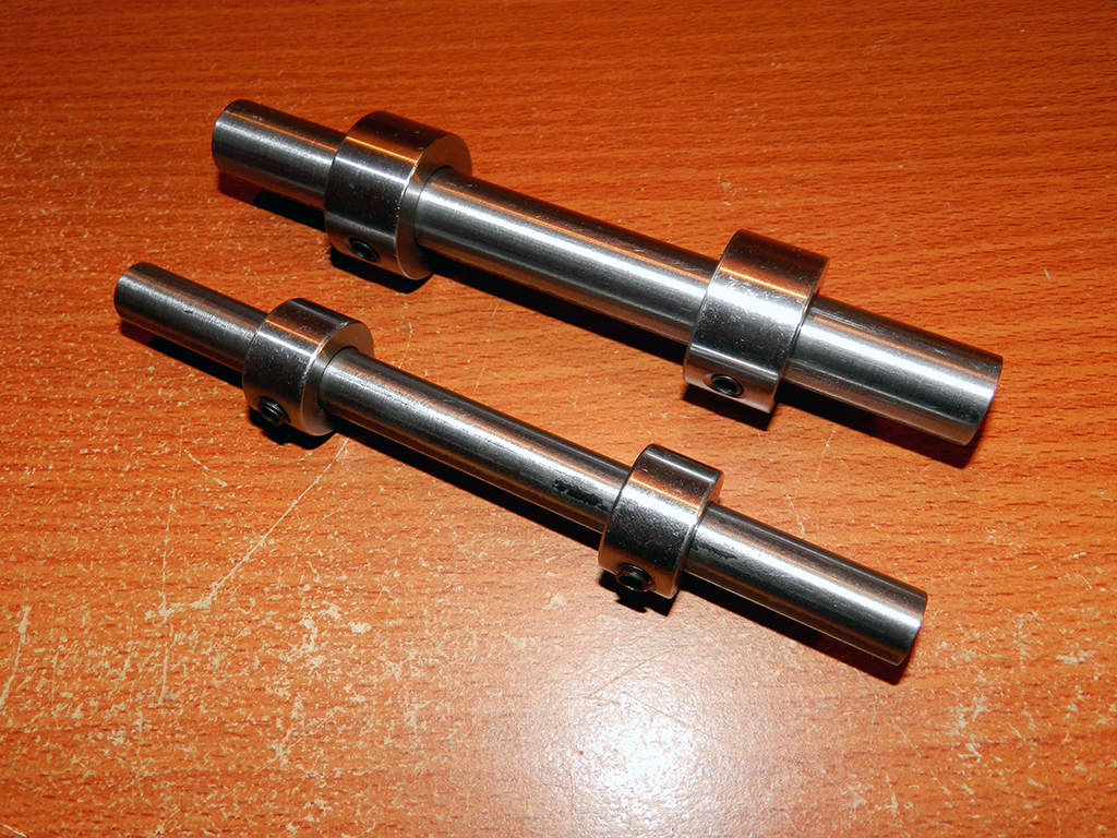
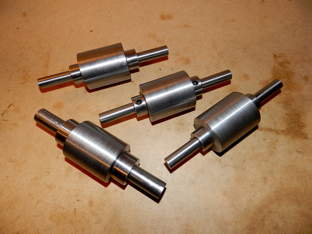
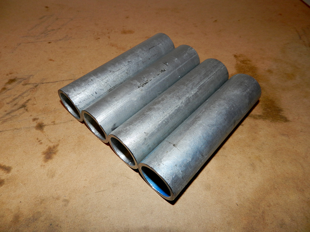
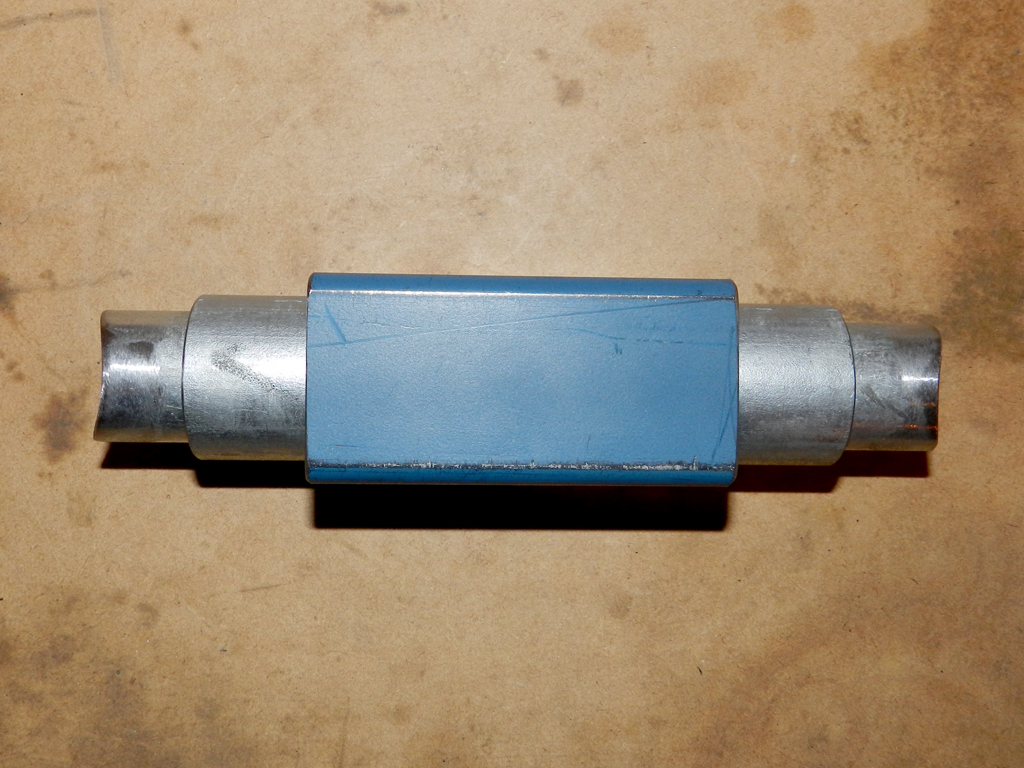
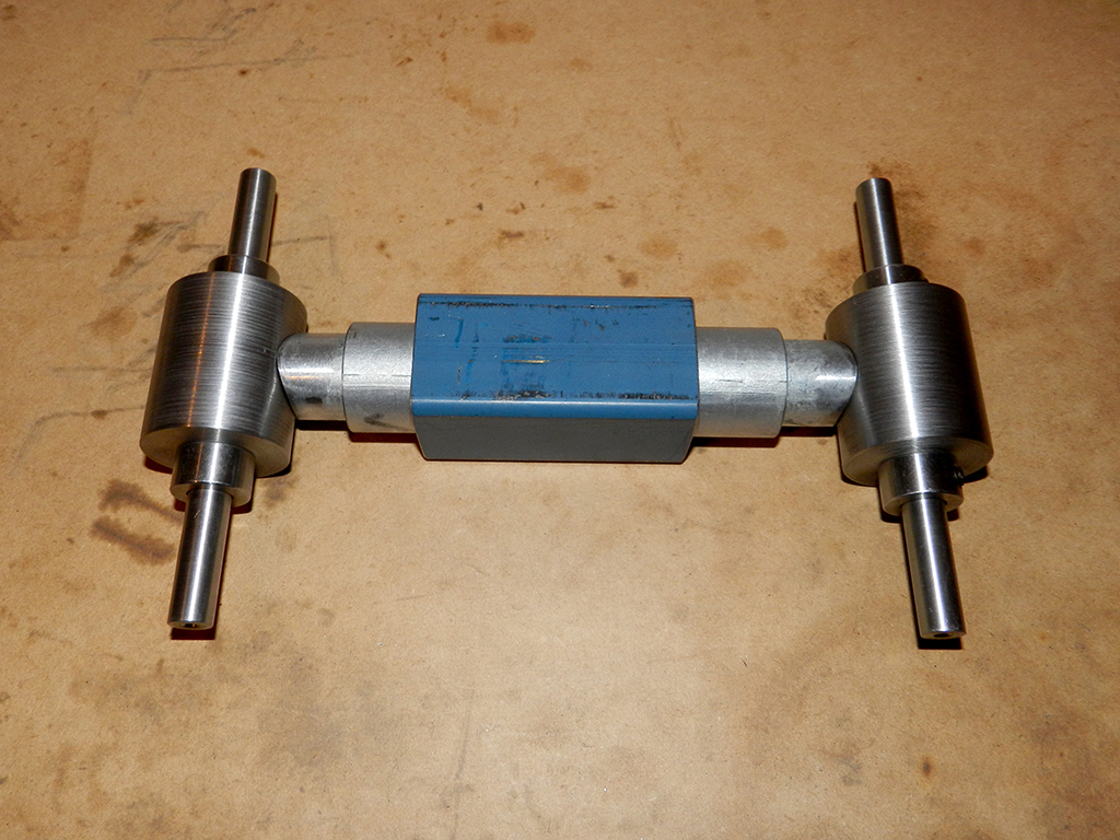
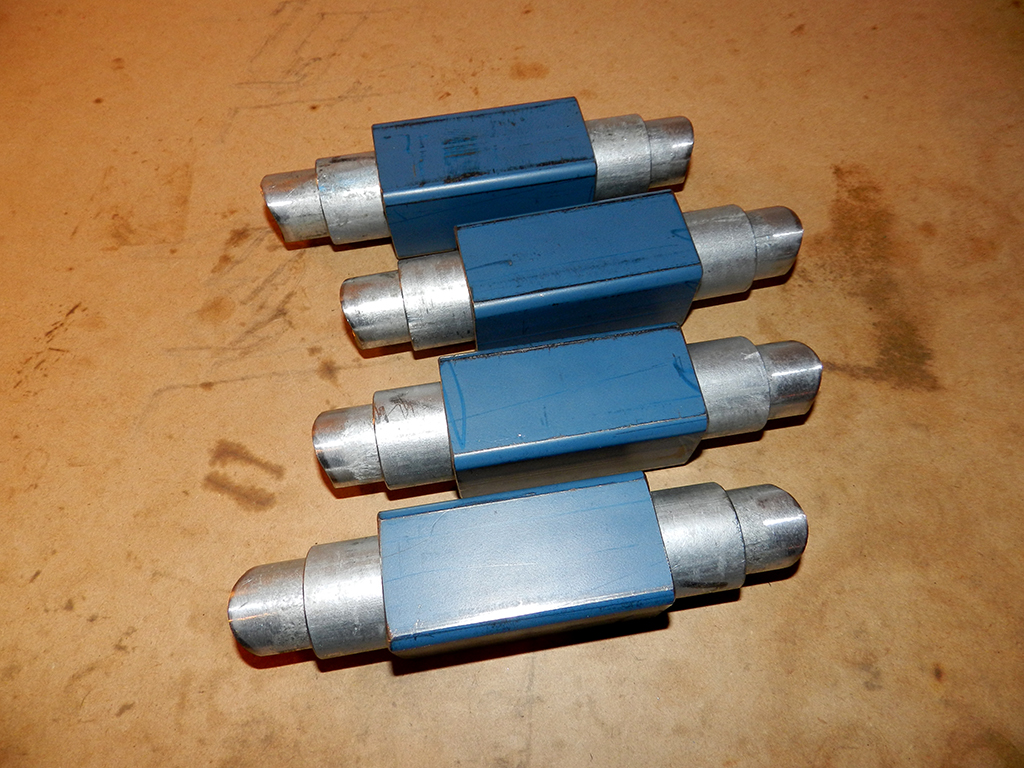
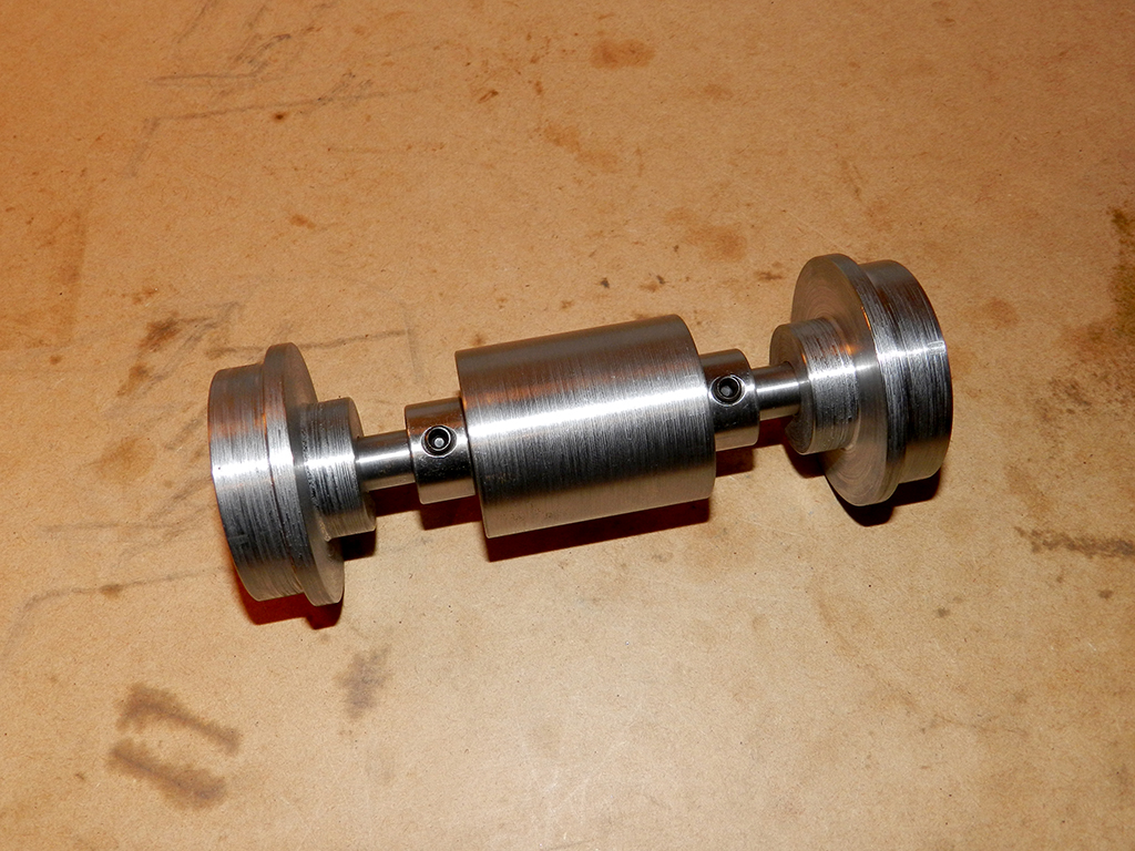
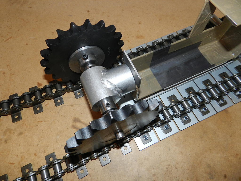
Made the other 2 axles for the prototype version of the motor mount/tensioner framing.
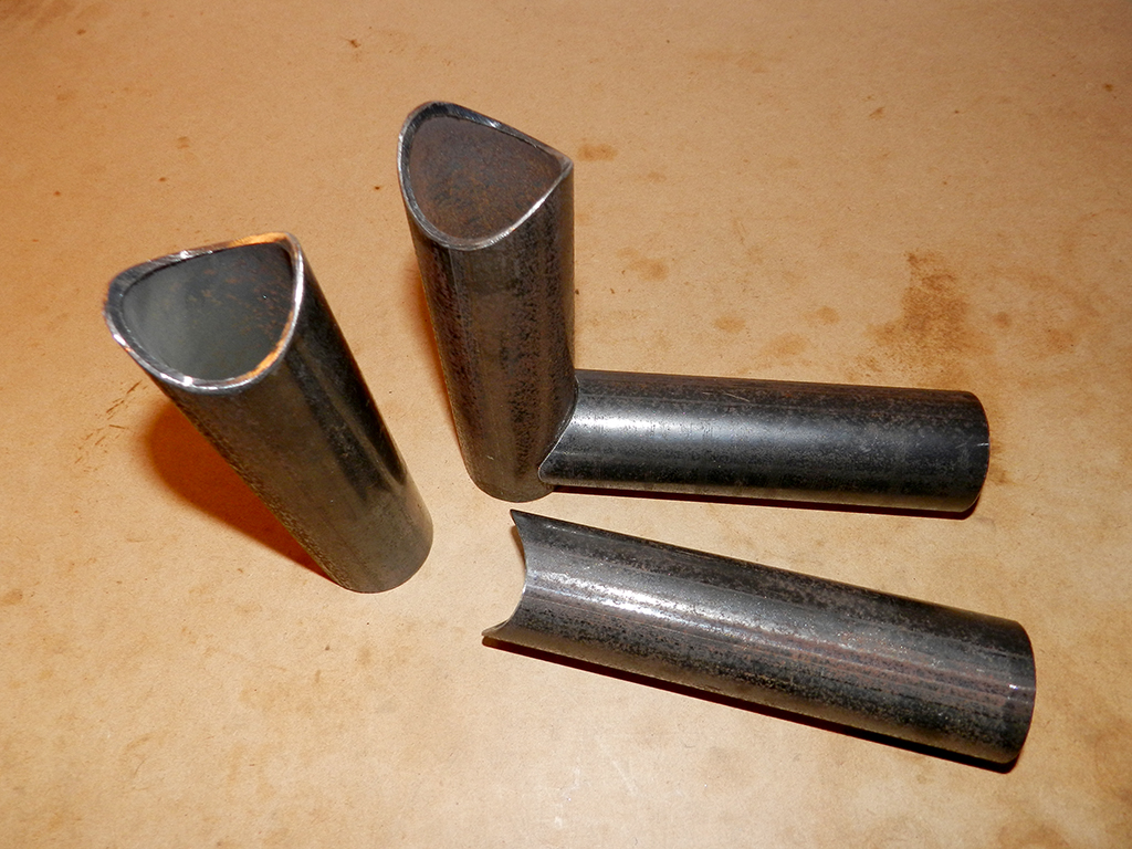
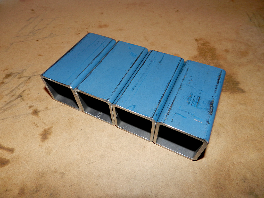
Notched both ends of this tube to make 2 parts out of it for connecting the front axle bearing holder to the motor mount.
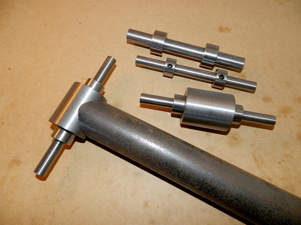
Started on making the prototype version of the motor mount.
Will do more on it tomorrow.
Notched both ends of this tube to make 2 parts out of it for connecting the front axle bearing holder to the motor mount.
Started on making the prototype version of the motor mount.
Will do more on it tomorrow.
Last edited:
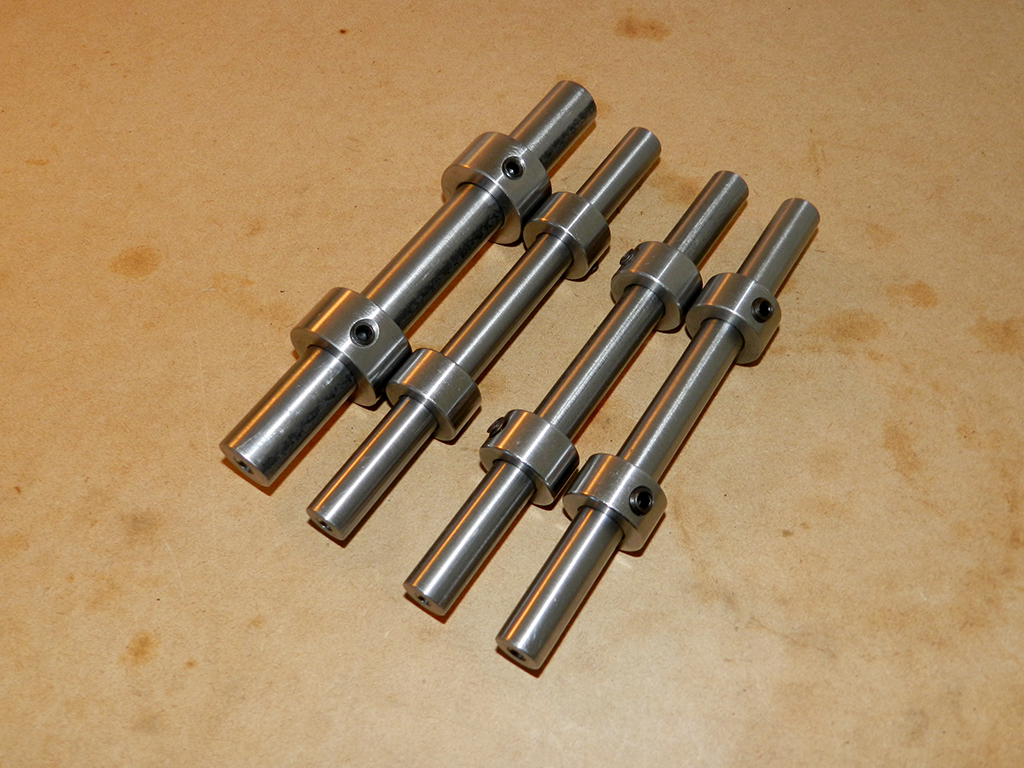
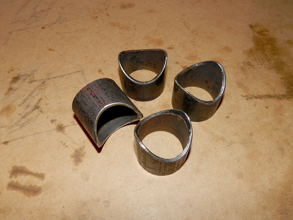
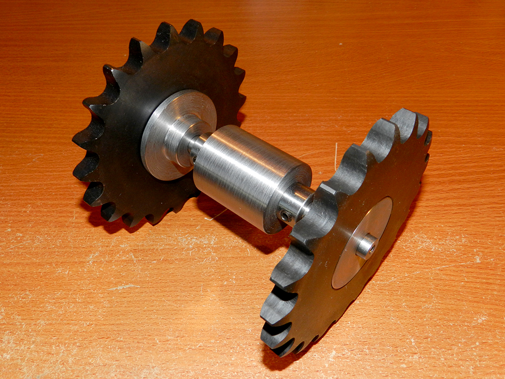
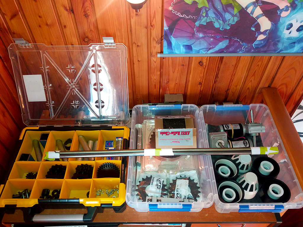
Notched tubes for holding front axle bearing housing. Did 2 extras.
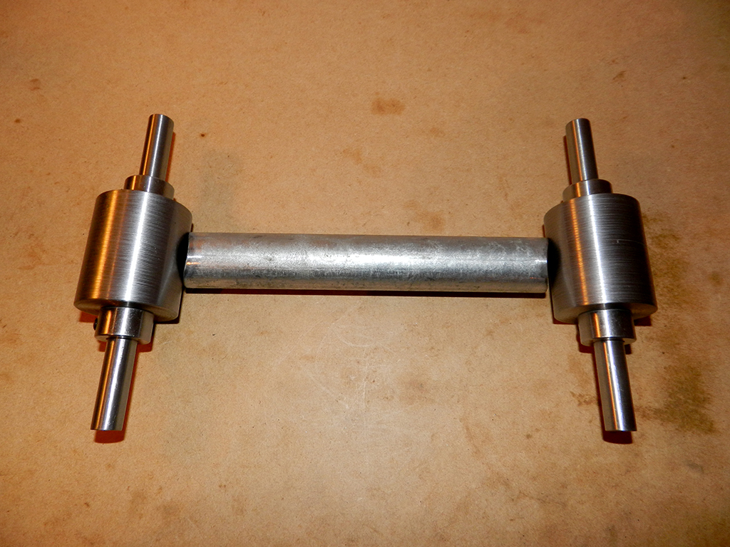
Axles and bearing housings sorted.
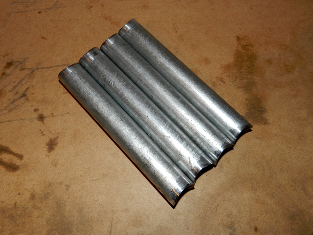
Started on the idle wheel tubes. Notching the ends.
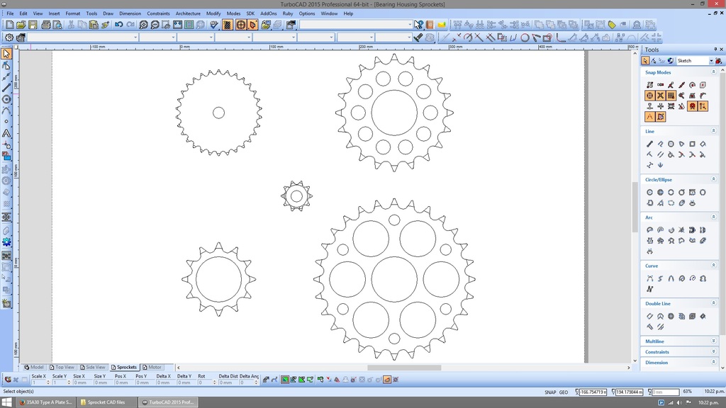
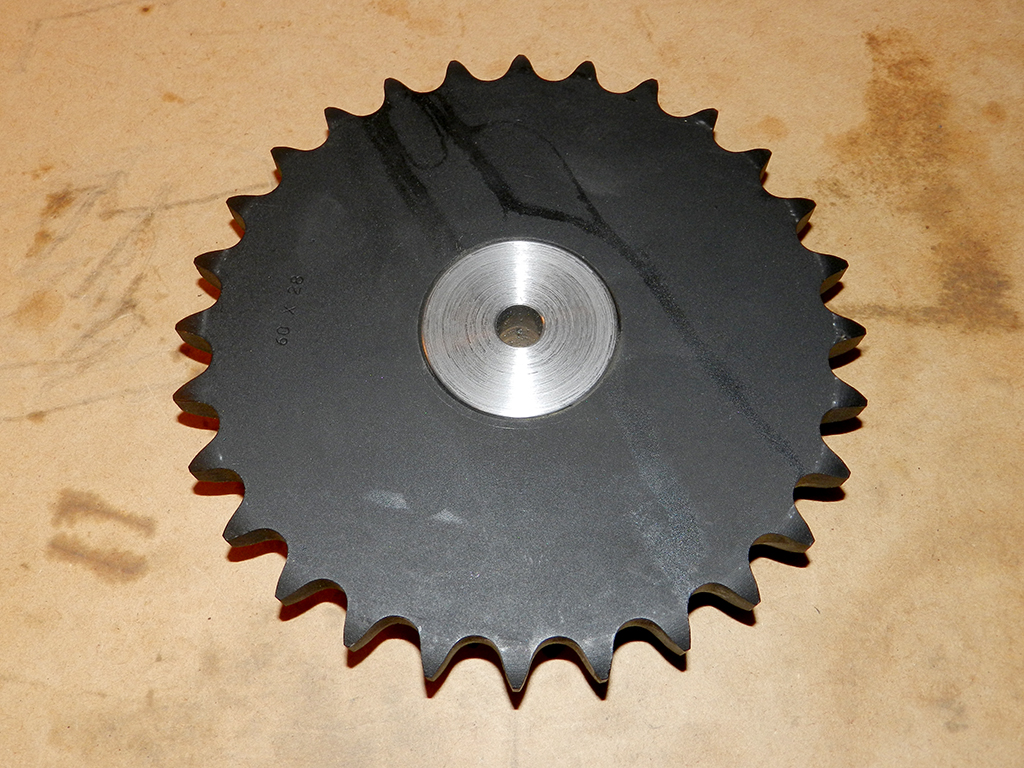
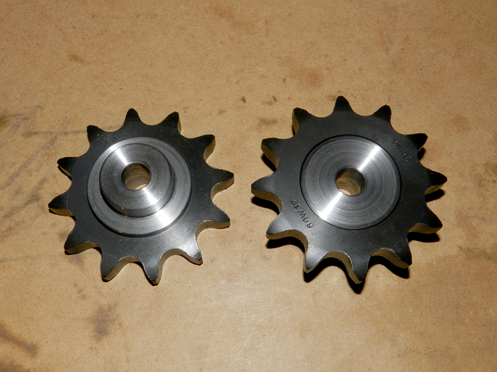
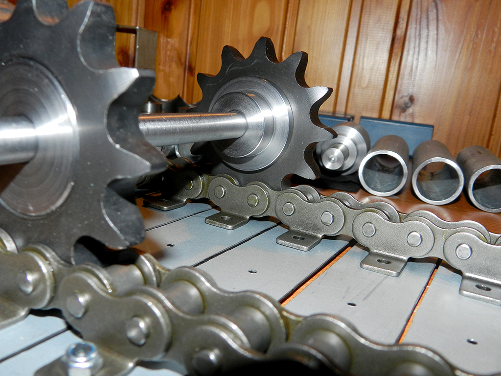
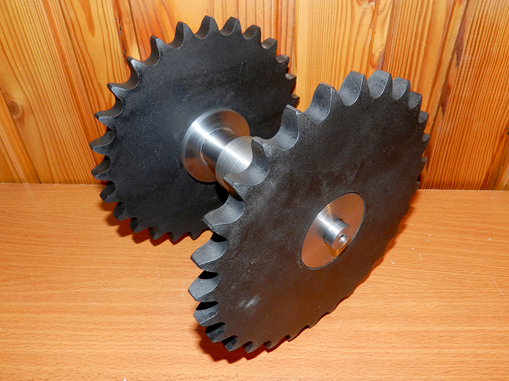
Sprockets. Holes drilled in the 2 bigger ones to remove some weight.
Do more on it tomorrow.
Axles and bearing housings sorted.
Started on the idle wheel tubes. Notching the ends.
Sprockets. Holes drilled in the 2 bigger ones to remove some weight.
Do more on it tomorrow.
Last edited:
Parts for the upper idle wheels.
How they go together.
Notched and shortened parts for the front wheel.
So far its going good.
Start on the sprocket hubs next.
How they go together.
Notched and shortened parts for the front wheel.
So far its going good.
Start on the sprocket hubs next.
Got the idle wheel parts sorted.
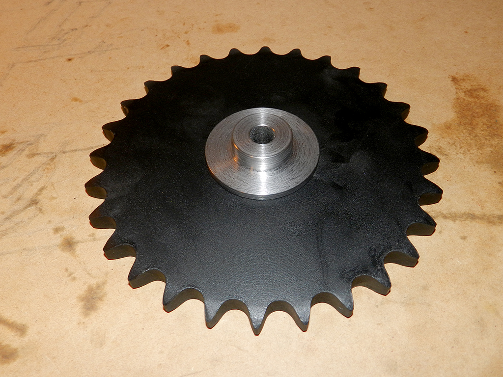
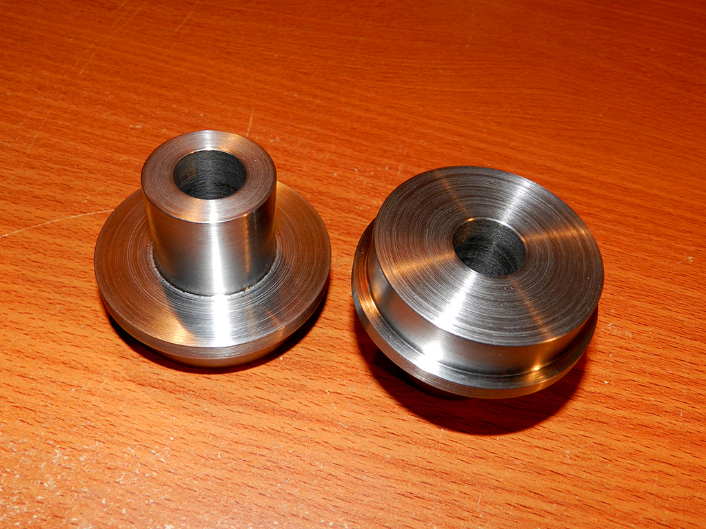
Made the hubs for the front sprockets.
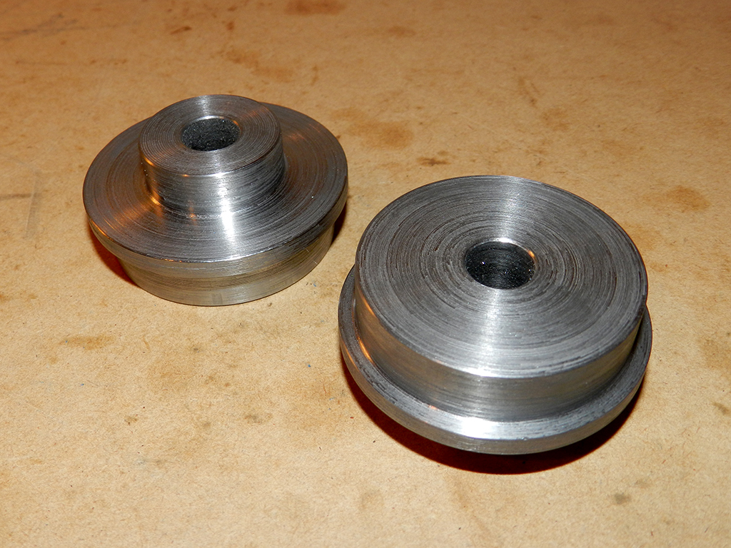
Doing more on it tonight.
Made the hubs for the front sprockets.
Doing more on it tonight.
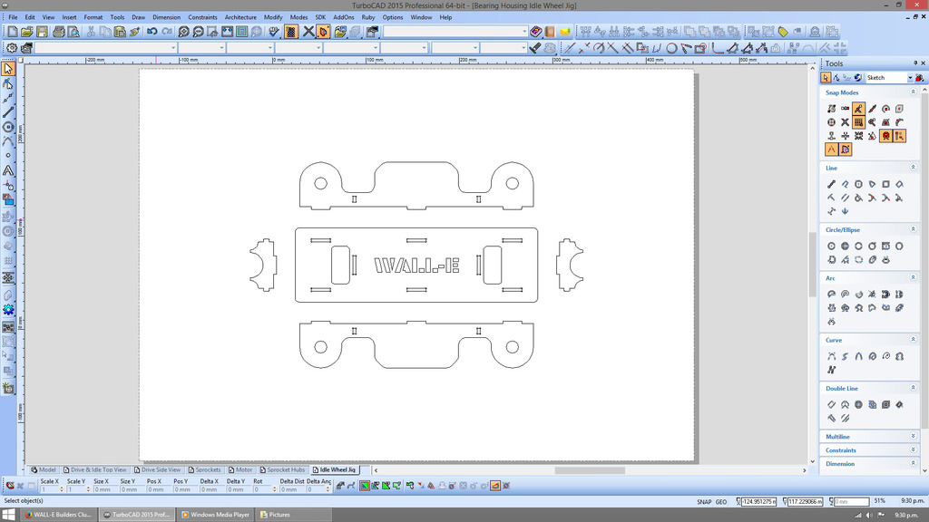
Got the Drawing done for the Idle wheel jig. Drawing up the jig for the drive wheels now. Oh and these are going to be used as building / tack welding jigs to get every thing straight and all the same length. Will be laser cut and then slotted together and welded.
Drawing of the parts for the upper idle wheel mount.
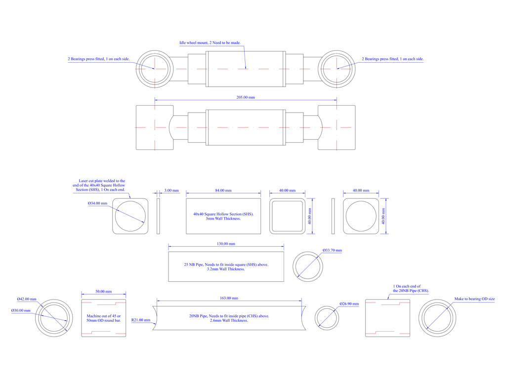
Drawing of the parts for the upper idle wheel mount.
Last edited:
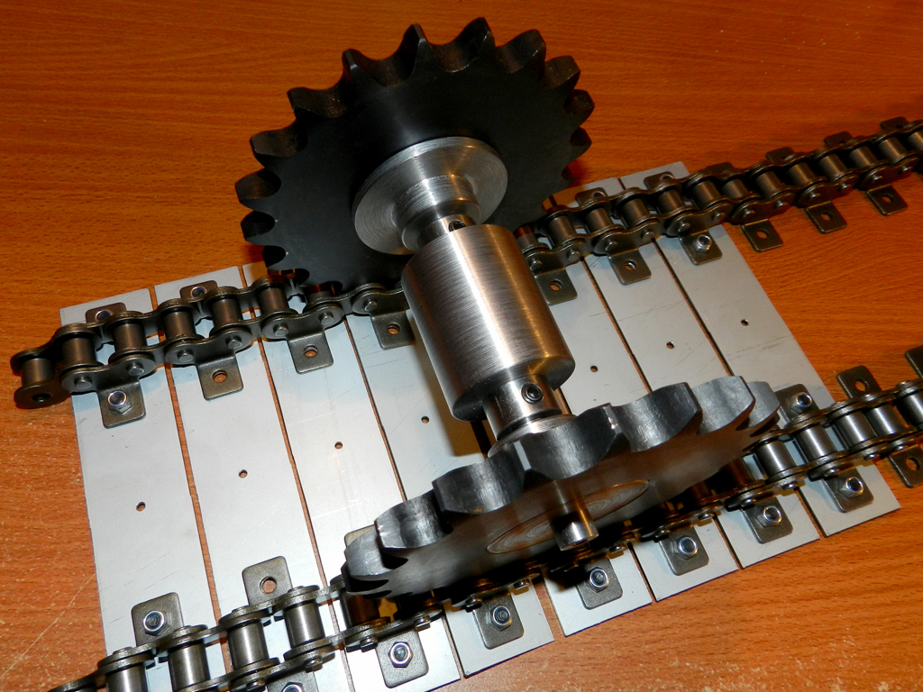
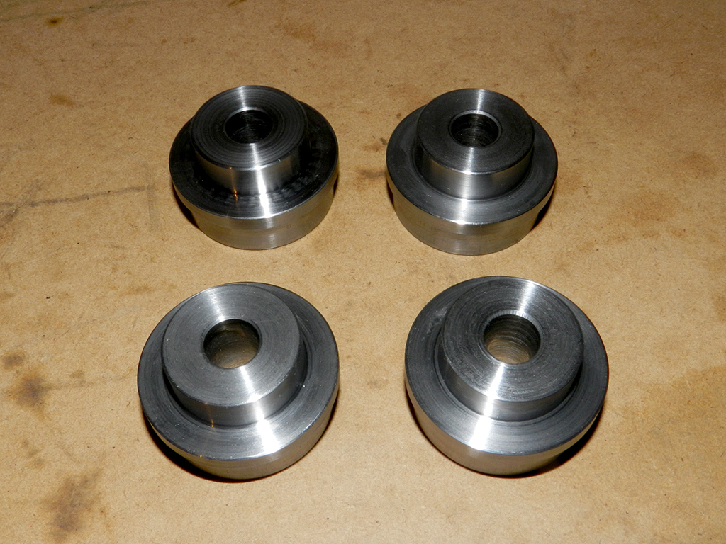
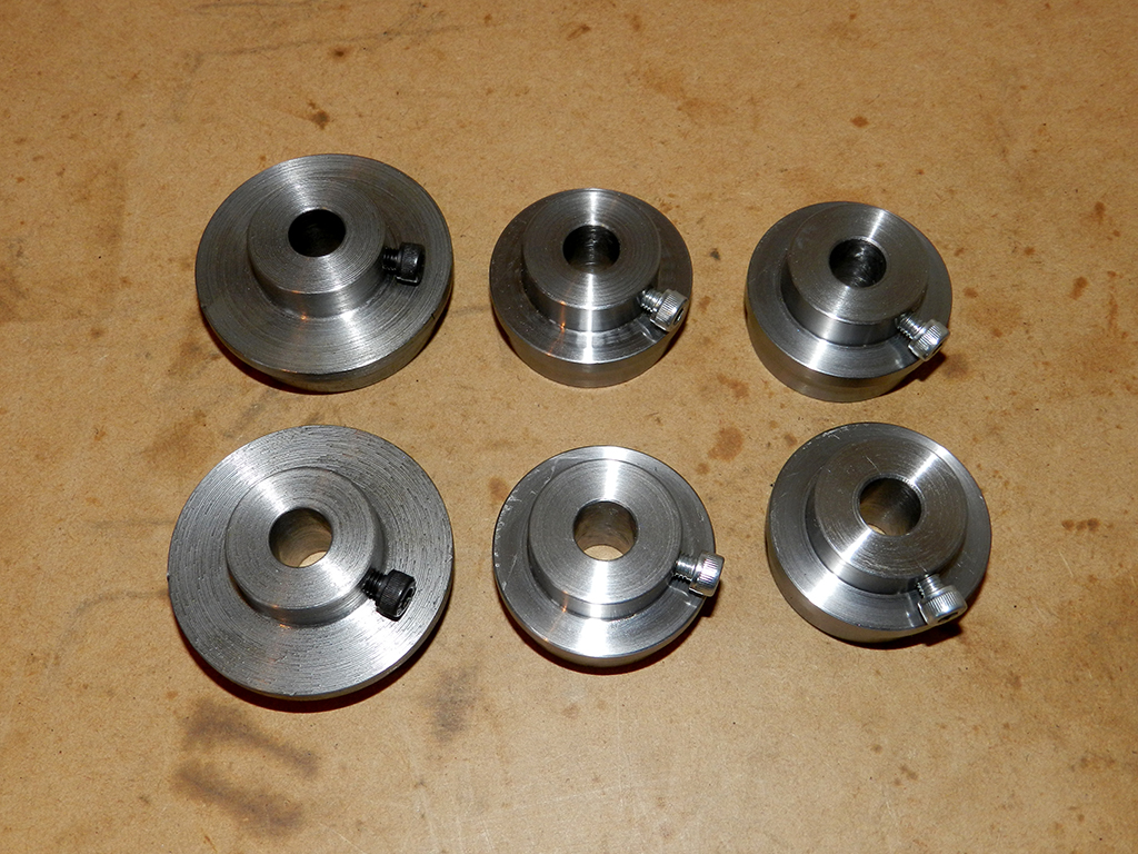
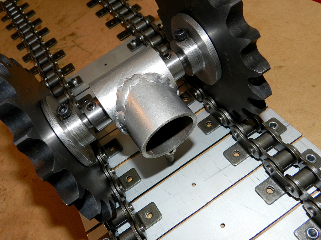
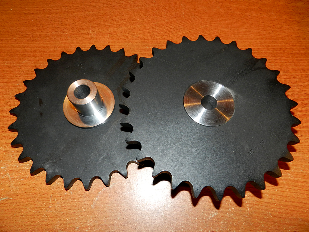
Got the hubs made for the idle wheel sprockets.
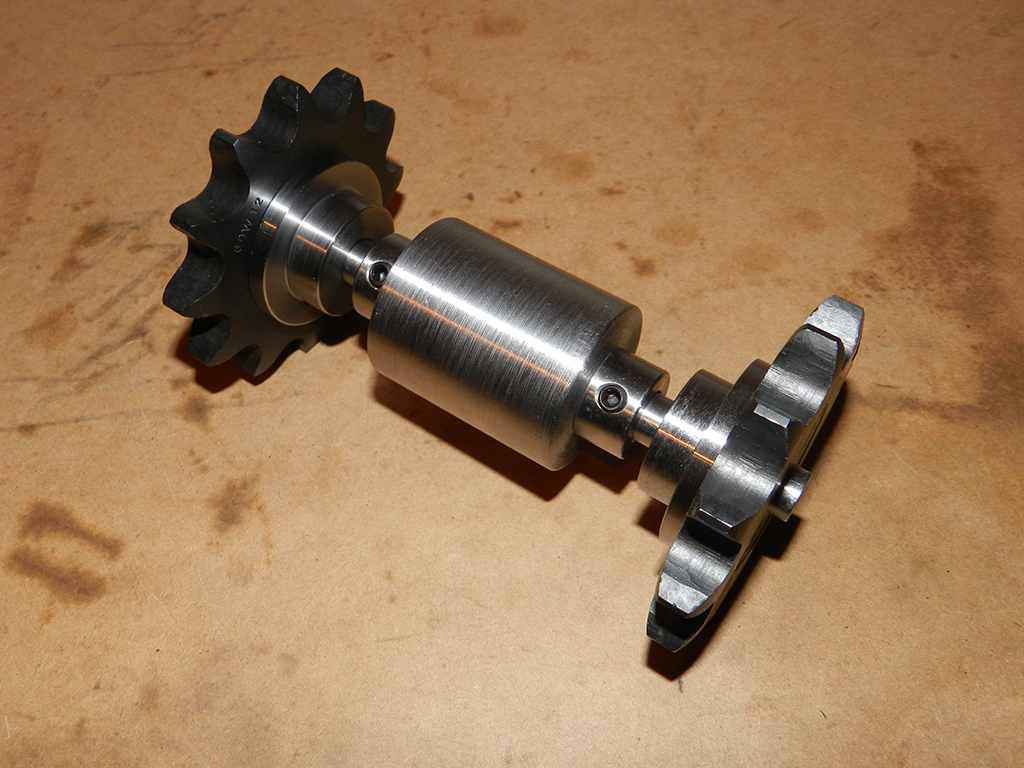
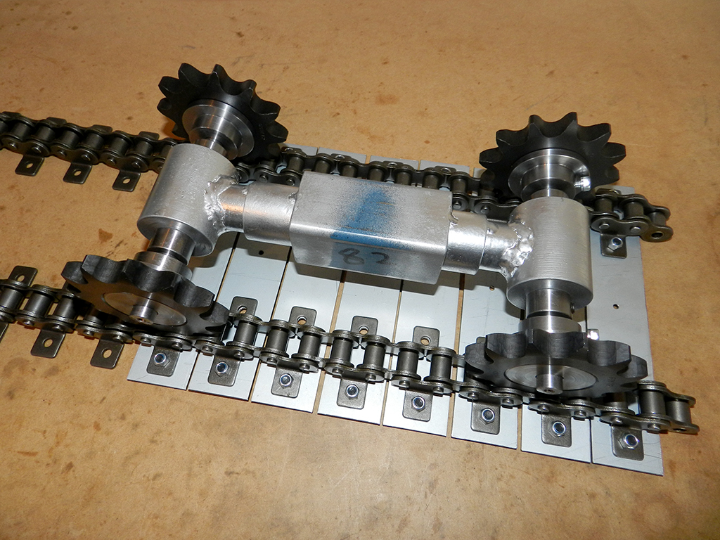
Lots of clearance.
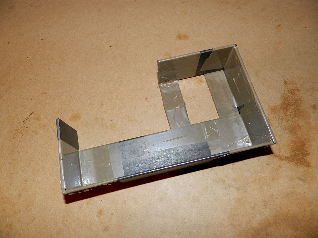
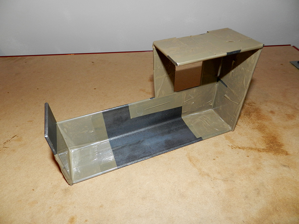
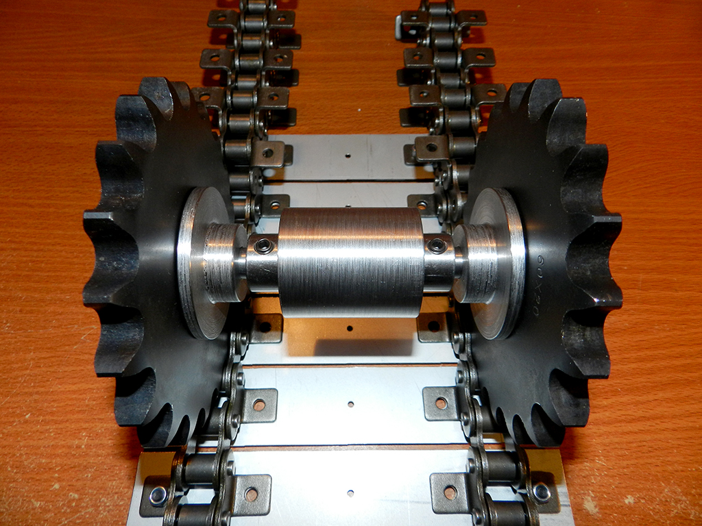
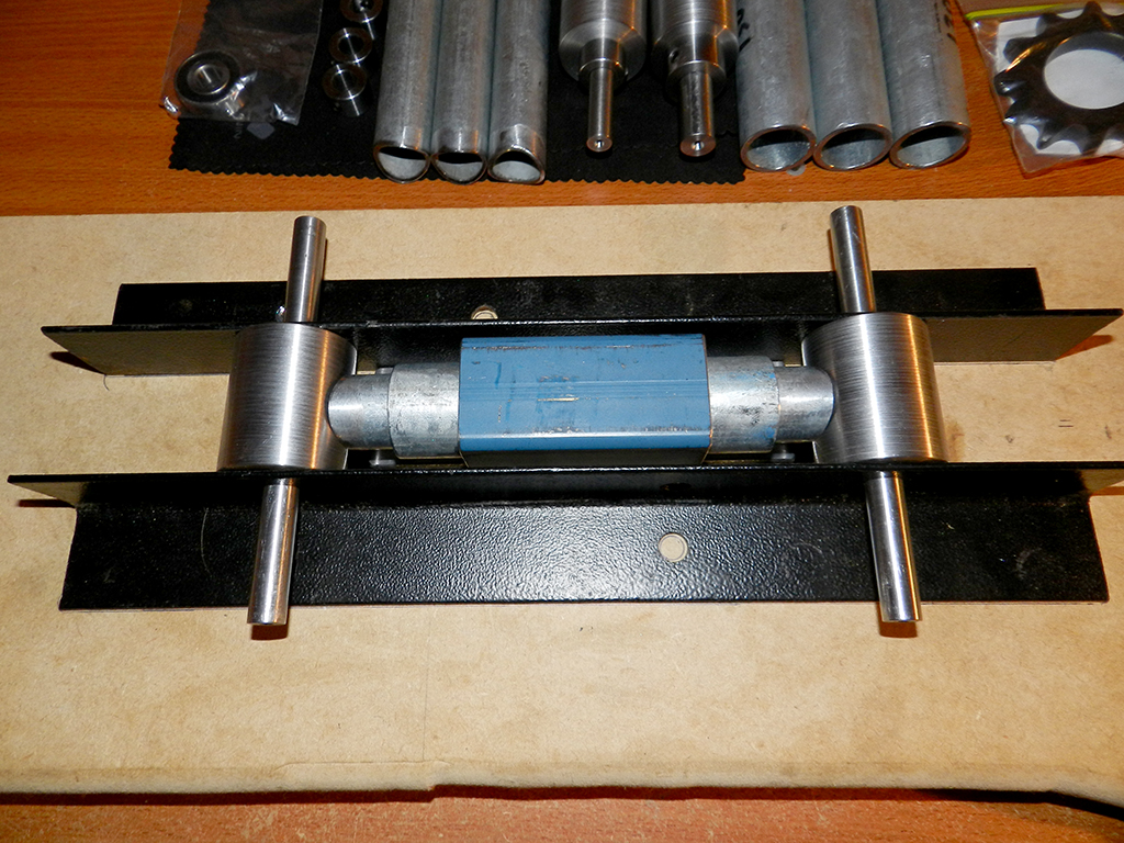
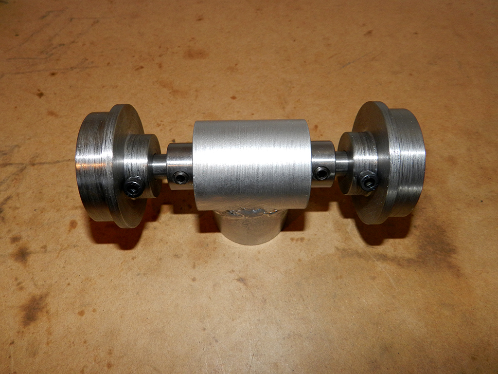
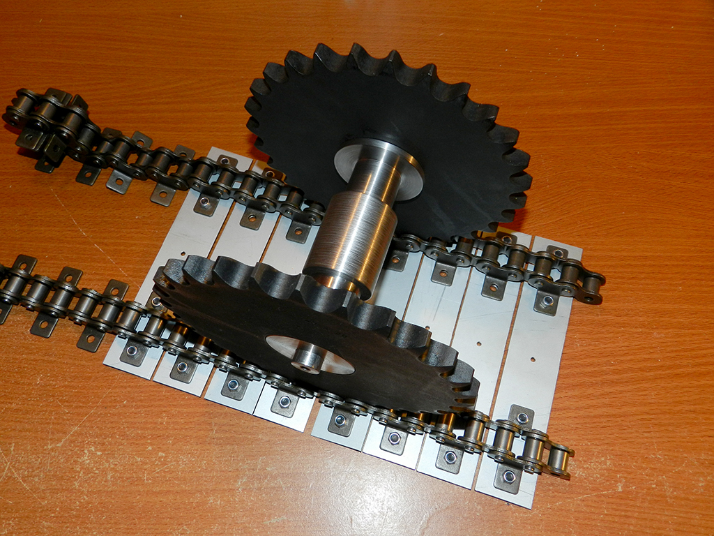
Temporary jig to build the prototype drive system.
Lots of clearance.
Temporary jig to build the prototype drive system.
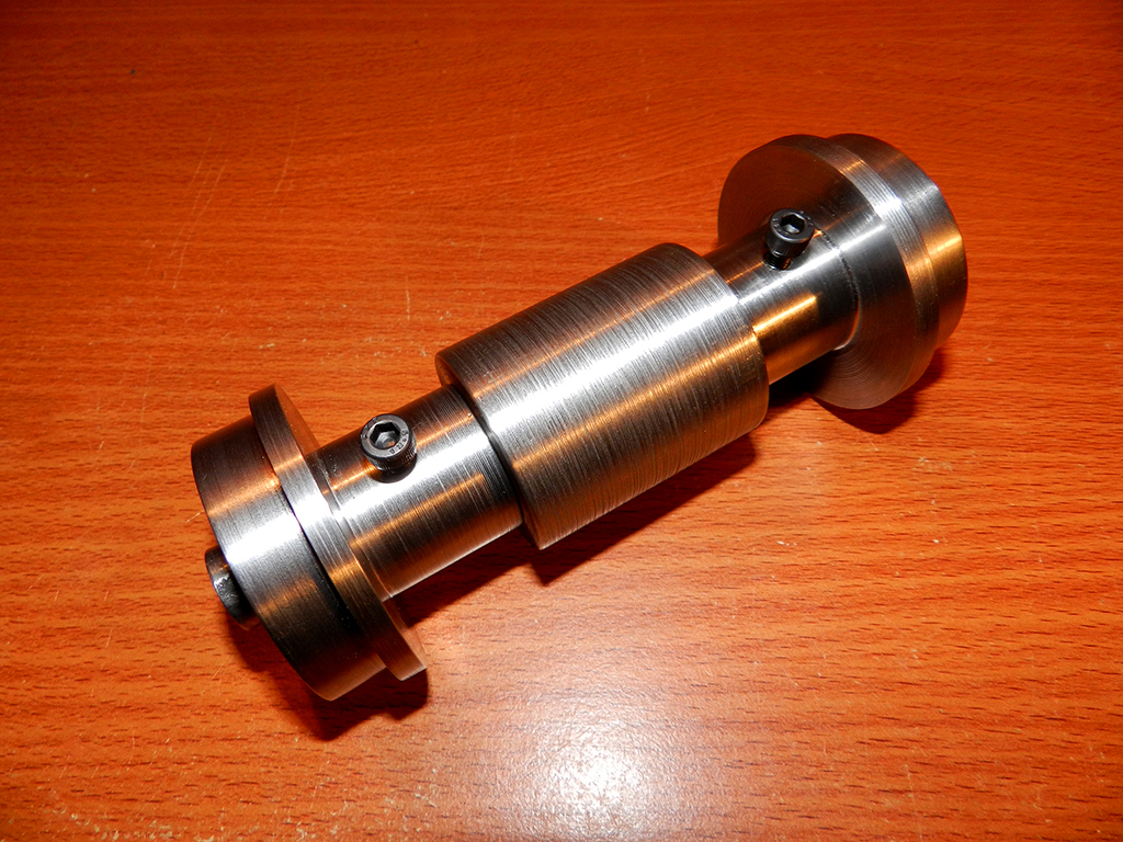
Installed grub screws in the hubs.
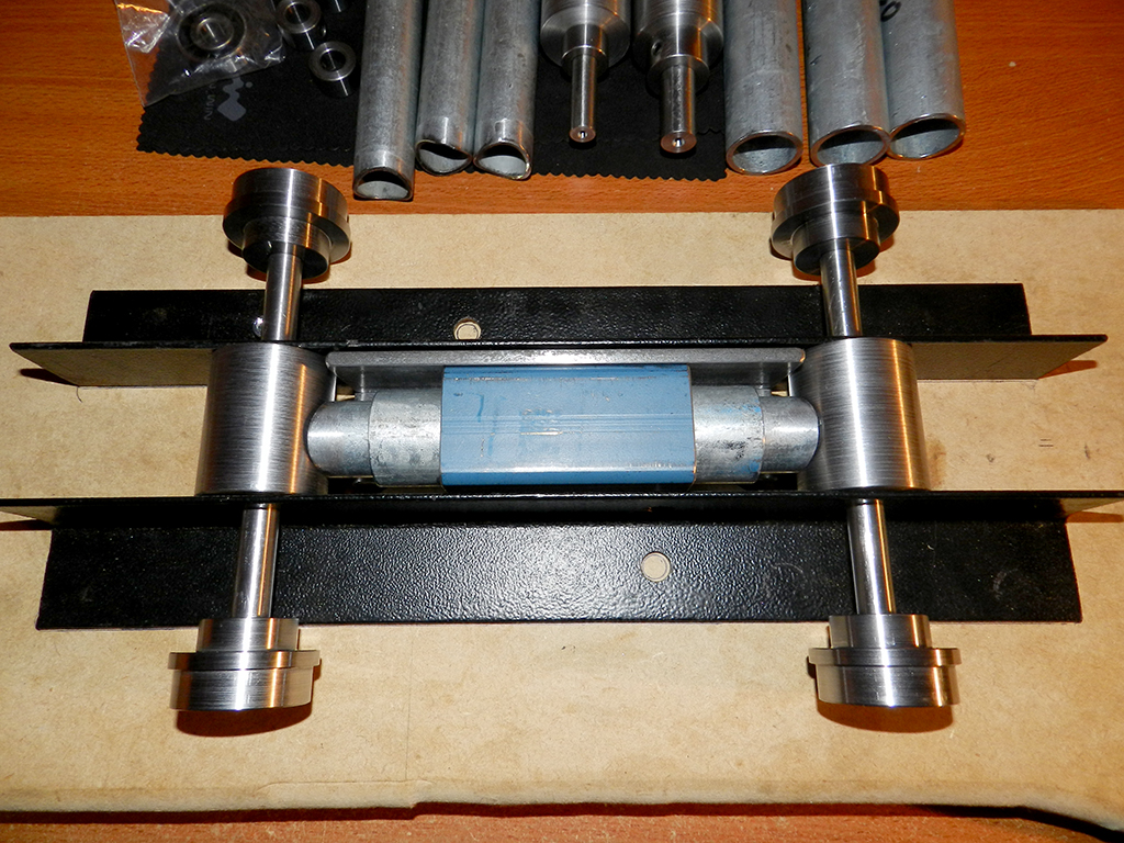
Jig worked out mint for the prototype system.
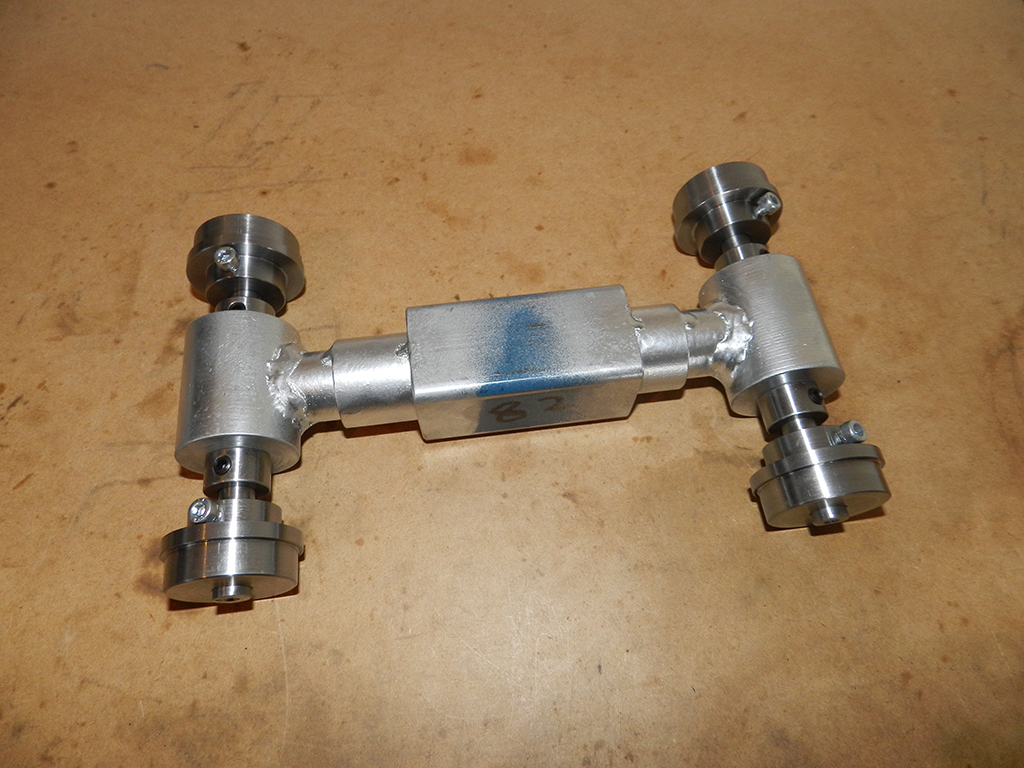
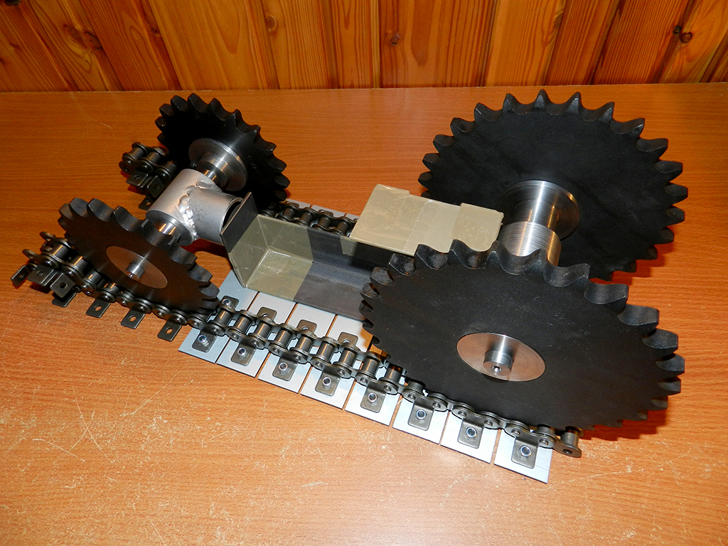
Got the front axle mount welded to the pipe also.
Test fit. Works good.")
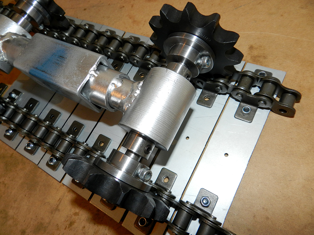
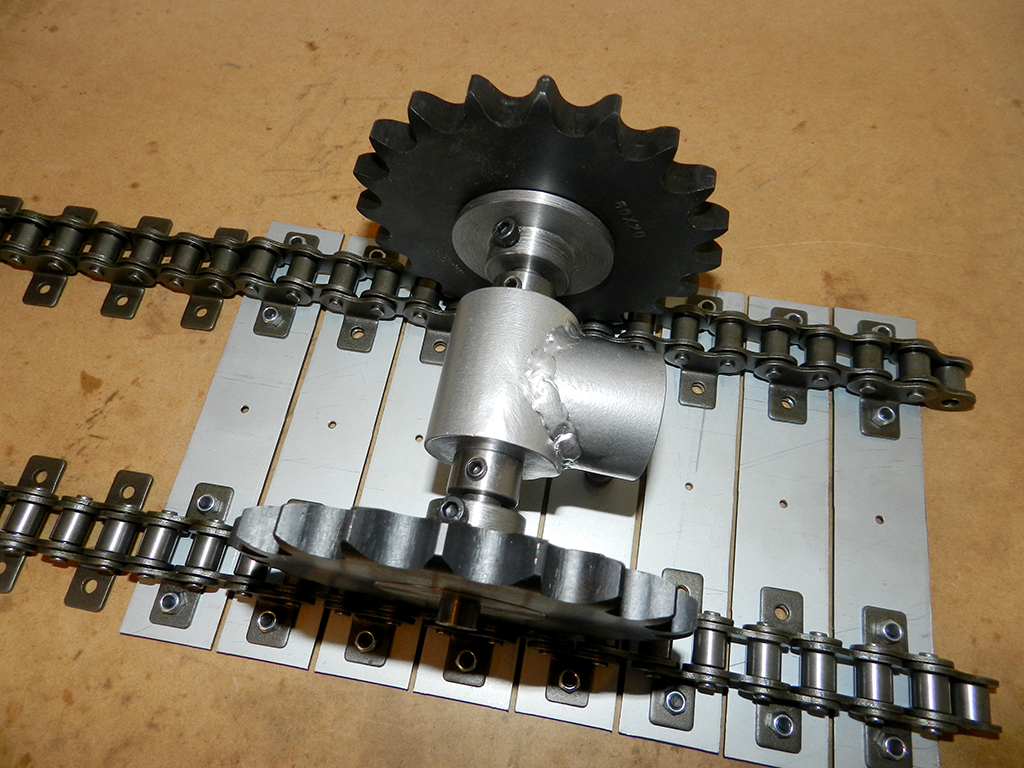
Now I have to start on the drive axle and motor mount then the tensioner.
Jig worked out mint for the prototype system.
Got the front axle mount welded to the pipe also.
Test fit. Works good.
Now I have to start on the drive axle and motor mount then the tensioner.
Was thinking about the drive last night. Why do you even need the shaft collars that are on the inside upto the bearing. Why not remove them and just install a steel/aluminum sleeve on the shaft in its space. The sprocket hubs are keyed and grub screwed in place on the axle to the width of the 2 attachment chains so if you made 2 sleeves the same size 1 on each side they would centre it all and make it a fixed width as they would be hard up to the centre of the bearing. Blue part is the sleeve in the drawing. What you think?

Just had a look in my photos folder and Mike Senna didn't use any collars on the original track system. He had the wheel hubs mounted on the axles all the way up to the bearings. I'm guessing he used shaft collars on his new track system like I'm building because he didn't have a lathe and was easier for him.

I was thinking why not just make the blue part (The steel sleeve) Make it part of the hub that way there is 1 less part to worry about.

Orange = Key, Pink = sprocket hub, grey = axle, green = bearing, black is the idle wheel arm/bearing holder. Hub is also grub screwed 1 onto the key and one 90 degrees from the key.

Doing it this way would be a matter of undoing 2 grub screws on the hub that has the sprocket on it to remove it from the axle and then the axle would come out the other side of the bearings with the other hub/sprocket still attached. Would need to remove the tracks 1st but that's just a matter of removing 2 chain connecting links.
If I used shaft collars I will have to remove the hub 1st then the shaft collar too remove the axle out the other side.
Just had a look in my photos folder and Mike Senna didn't use any collars on the original track system. He had the wheel hubs mounted on the axles all the way up to the bearings. I'm guessing he used shaft collars on his new track system like I'm building because he didn't have a lathe and was easier for him.
I was thinking why not just make the blue part (The steel sleeve) Make it part of the hub that way there is 1 less part to worry about.
Orange = Key, Pink = sprocket hub, grey = axle, green = bearing, black is the idle wheel arm/bearing holder. Hub is also grub screwed 1 onto the key and one 90 degrees from the key.
Doing it this way would be a matter of undoing 2 grub screws on the hub that has the sprocket on it to remove it from the axle and then the axle would come out the other side of the bearings with the other hub/sprocket still attached. Would need to remove the tracks 1st but that's just a matter of removing 2 chain connecting links.
If I used shaft collars I will have to remove the hub 1st then the shaft collar too remove the axle out the other side.
What I have come up with. 4 parts less and easier to take apart. 2 grub screws to loosen and then one of the hubs/sprockets can be removed then remove the key and slide the axle out the other side of bearings with the other hub/sprocket attached on axle with its key in place.

Just made a logo for my blog.

Speedyslyder will remember this logo from the rendered logo video I made ages ago. Changed it a little.
Speedyslyder will remember this logo from the rendered logo video I made ages ago. Changed it a little.
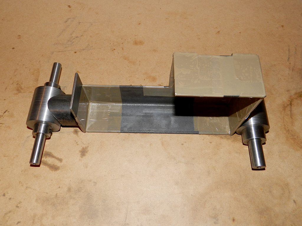
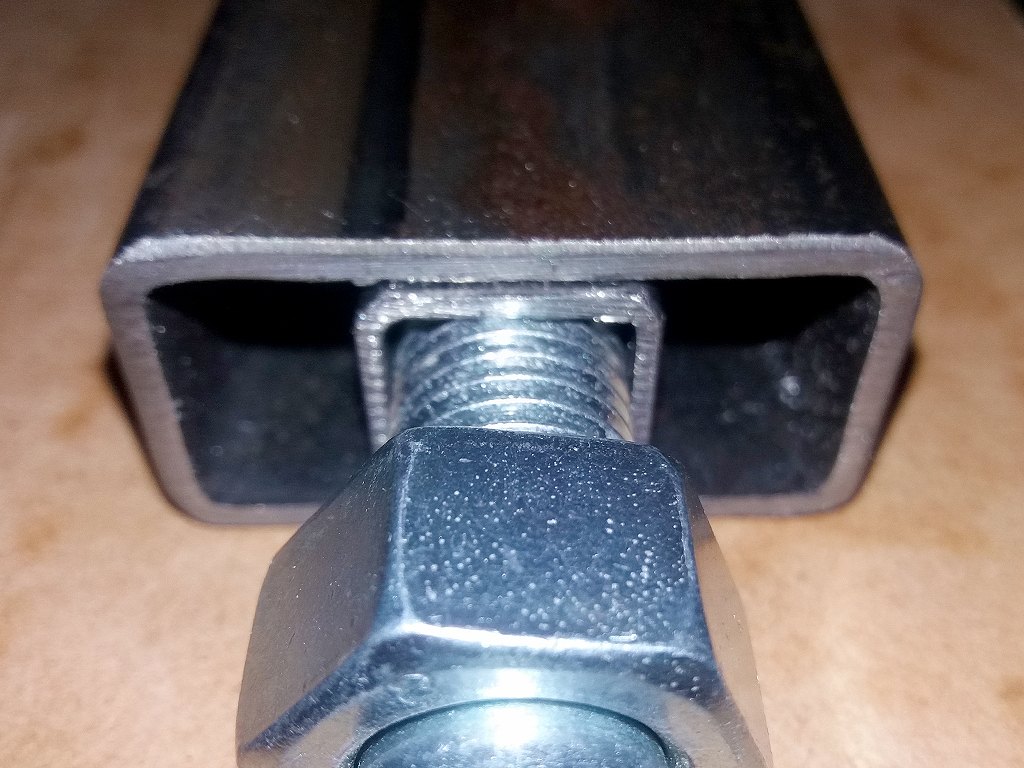
How the adjuster will be made for tensioning the track. The 50x25x2.5 RHS will have a plate welded on the end of it with a hole in the centre for the threaded rod to go through and into the 20x20x1.6 SHS. A nut will be also welded to the plate on the end of the 50x25x2.5 RHS.
Set screws installed.
I think I may have made to many. Still need to make more of the front mount mount notched tube and notch the ends of the idle arm tubes for the bearing mount.
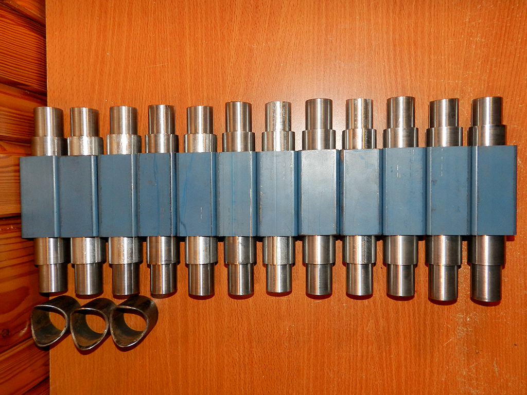
I think I may have made to many. Still need to make more of the front mount mount notched tube and notch the ends of the idle arm tubes for the bearing mount.
Similar threads
- Replies
- 5
- Views
- 1K